Controller of injection molding machine

Inactive Publication Date: 2005-11-03
FANUC LTD
View PDF9 Cites 8 Cited by
  • Summary
  • Abstract
  • Description
  • Claims
  • Application Information

AI Technical Summary

Benefits of technology

[0016] Since the injection molding machine having the toggle type mold clamping apparatus of the present invention has the above-described structures, a mold clamping force can be maintained at a constant set mold clamping force even if the mold temperature

Problems solved by technology

Thus, even if the crosshead is positioned to the initial predetermined position, the mold clamping force can not be maintained at the set mold clamping force.
According to this method, however, since it is necessary to provide a mold clamping force detector such as a mold temperature sensor or a distortion sensor, costs of the apparatus are increased.
However, there is a problem that if the die height is ad

Method used


Image

  • Controller of injection molding machine
  • Controller of injection molding machine
  • Controller of injection molding machine

Examples


Embodiment Construction

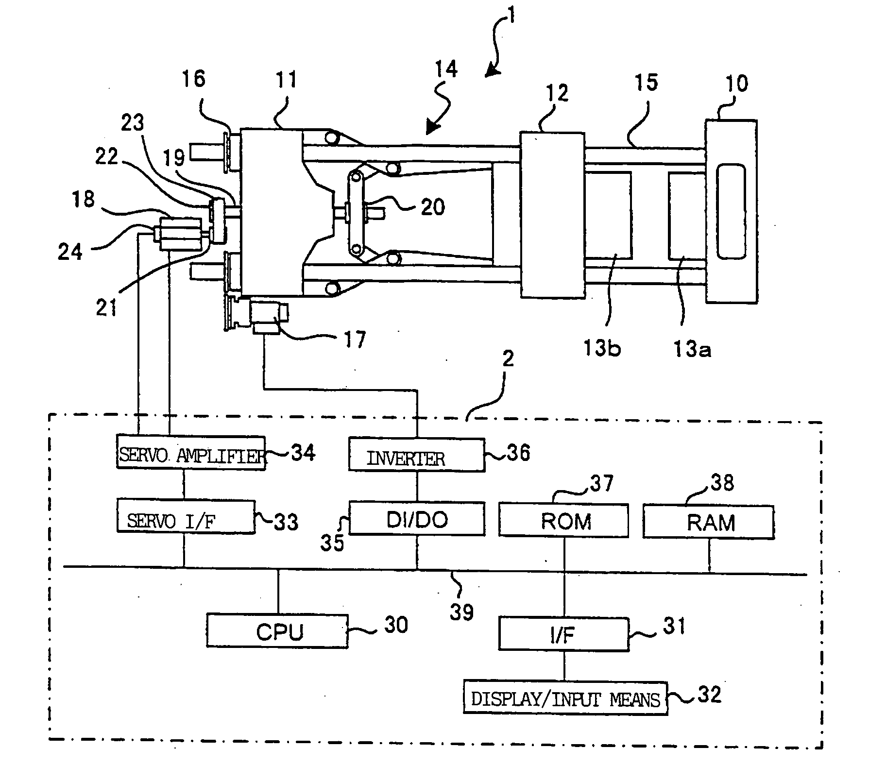
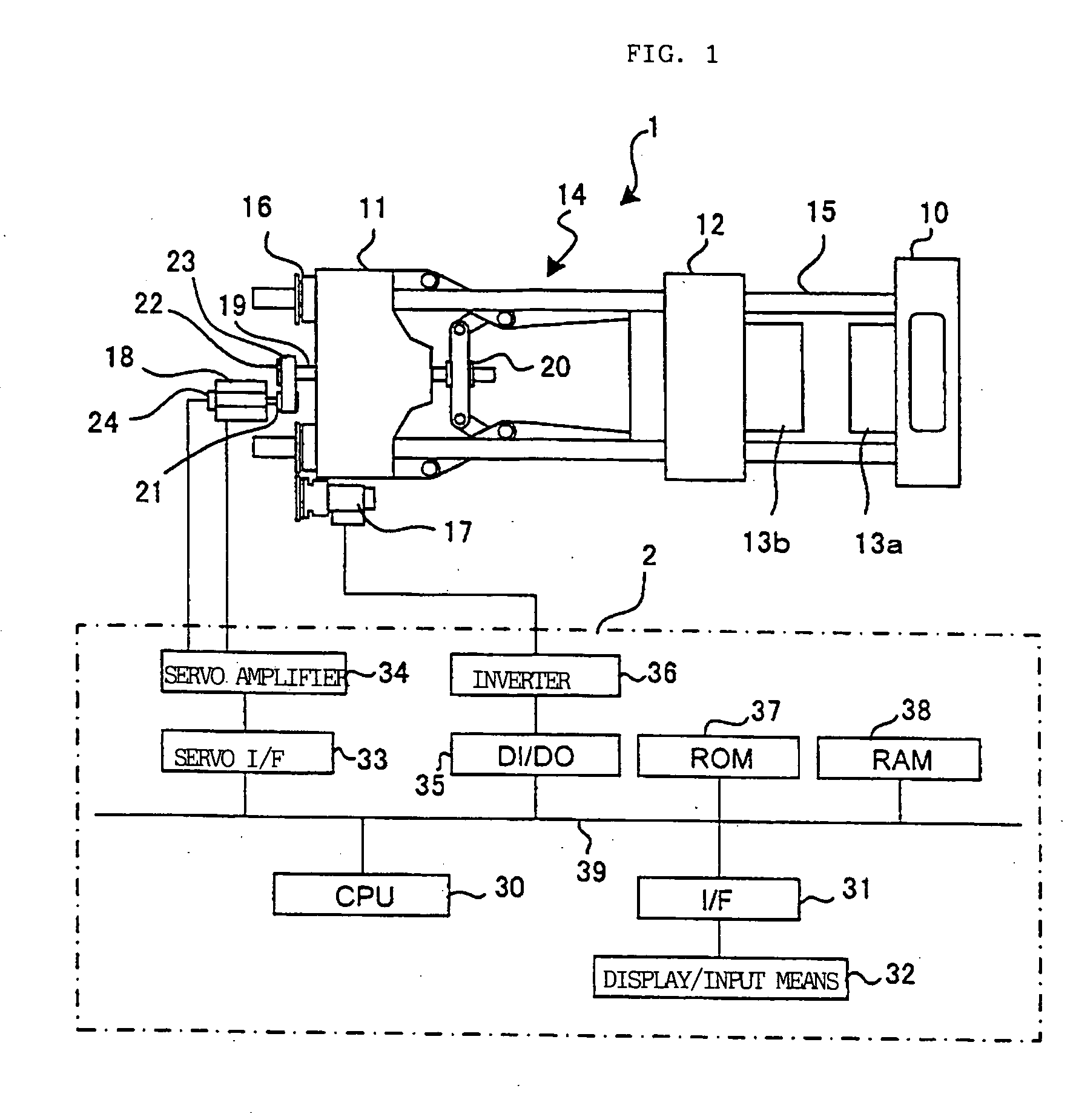
[0021]FIG. 1 is an explanatory view of an embodiment of the present invention. In FIG. 1, a reference numeral 1 represents a toggle type mold clamping apparatus, and a reference numeral 2 represents a controller of an injection molding machine having the toggle type mold clamping apparatus 1. A fixed platen 10 and a rear platen 11 are connected to each other through a plurality of tie bars 15. A movable platen 12 is disposed between the fixed platen 10 and the rear platen 11 such that the movable platen 12 is guided by the tie bar 15. A fixed mold 13a is detachably mounted on the fixed platen 10, and a movable mold 13b is detachably mounted on the movable platen 12.

[0022] A toggle mechanism 14 is disposed between the rear platen 11 and the movable platen 12. The rear platen 11 is provided with a mold clamping servomotor 18 for driving the toggle mechanism 14 and a ball screw 19.

[0023] The ball screw 19 is mounted on the rear platen 11 such that the ball screw 19 can rotate but can...


PUM

PropertyMeasurementUnit
Forceaaaaaaaaaa

Abstract

A crosshead position Cf for obtaining a set mold clamping force is obtained based on a mold touch position Ct obtained in mold clamping process in immediately preceding molding cycle, and a crosshead is allowed to move to the position Cf. During that time, it is determined whether a load La of a servomotor for mold clamping operation which drives a toggle mechanism exceeds a judgment load Ls, and a crosshead position Ca when the load La exceeds the judgment load Ls is stored as a mold touch position. In the next molding cycle, a crosshead position Cf where the set mold clamping force is obtained is obtained based on this stored mold touch position.

Description

BACKGROUND OF THE INVENTION [0001] 1. Field of the Invention [0002] The present invention relates to a controller of an injection molding machine, and more particularly, to a controller which maintains a mold clamping force in a toggle type mold clamping apparatus at a constant level. [0003] 2. Description of the Prior Art [0004] In a toggle type mold clamping apparatus in an injection molding machine, a movable mold abuts against a fixed mold and then, the movable mold (or movable platen on which the movable mold is mounted) is moved, a tie bar which connects a fixed platen on which the fixed mold is mounted and a rear platen on which the toggle type mold clamping apparatus is mounted with each other is expanded, thereby generating a mold clamping force. When the mold is replaced, the thickness adjustment for adjusting a position of the rear platen is carried out such that a set mold clamping force can be obtained when a crosshead of the toggle type mold clamping apparatus reaches ...

Claims


Application Information

Patent Timeline
IPC IPC(8): B29C45/66B29C45/17B29C45/76B29C45/80
CPCB29C45/1751B29C45/7653B29C2945/76013B29C2945/76083B29C2945/7612B29C2945/76217B29C2945/76943B29C2945/76531B29C2945/76568B29C2945/76702B29C2945/76933B29C2945/76939B29C2945/76505
Inventor UCHIYAMA, TATSUHIROWATANABE, HIROSHI
Owner FANUC LTD
Why Eureka
Try Eureka