Hybrid bipolar plate assembly and devices incorporating same

a technology of bipolar plates and components, applied in the direction of cell components, cell component details, electrochemical generators, etc., can solve the problems of significant performance and efficiency loss, hydrogen in the coolant loop, and the typical small voltage provided by a single cell unit for useful applications

a technology of bipolar plates and components, applied in the direction of cell components, cell component details, electrochemical generators, etc., can solve the problems of significant performance and efficiency loss, hydrogen in the coolant loop, and the typical small voltage provided by a single cell unit for useful applications

US20050244700A1Inactive Publication Date: 2005-11-03GM GLOBAL TECH OPERATIONS LLC

Image

  • Hybrid bipolar plate assembly and devices incorporating same
  • Hybrid bipolar plate assembly and devices incorporating same
  • Hybrid bipolar plate assembly and devices incorporating same

Examples


Embodiment Construction

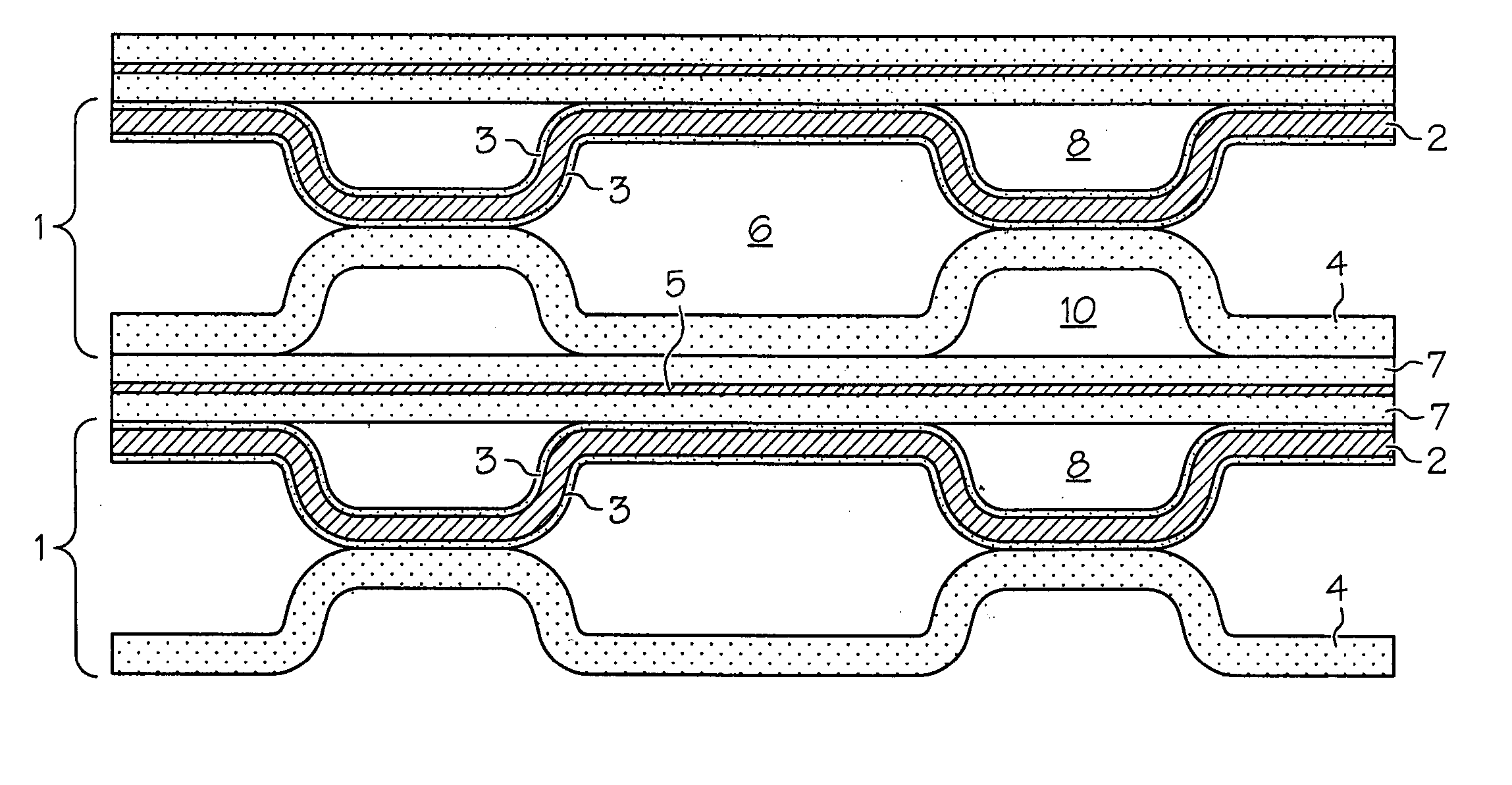
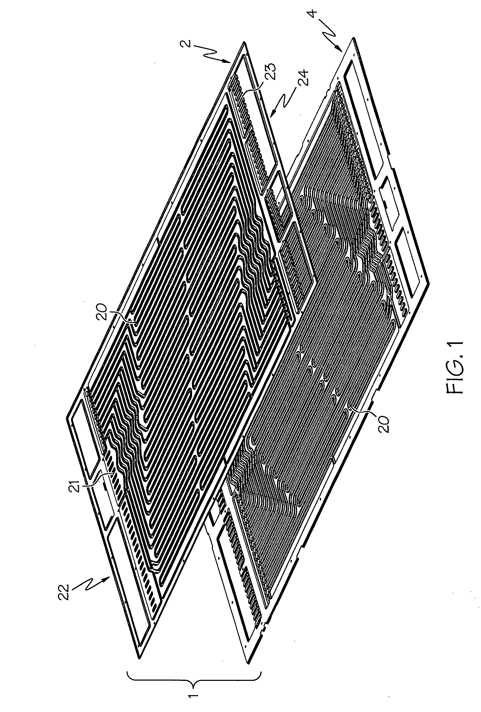
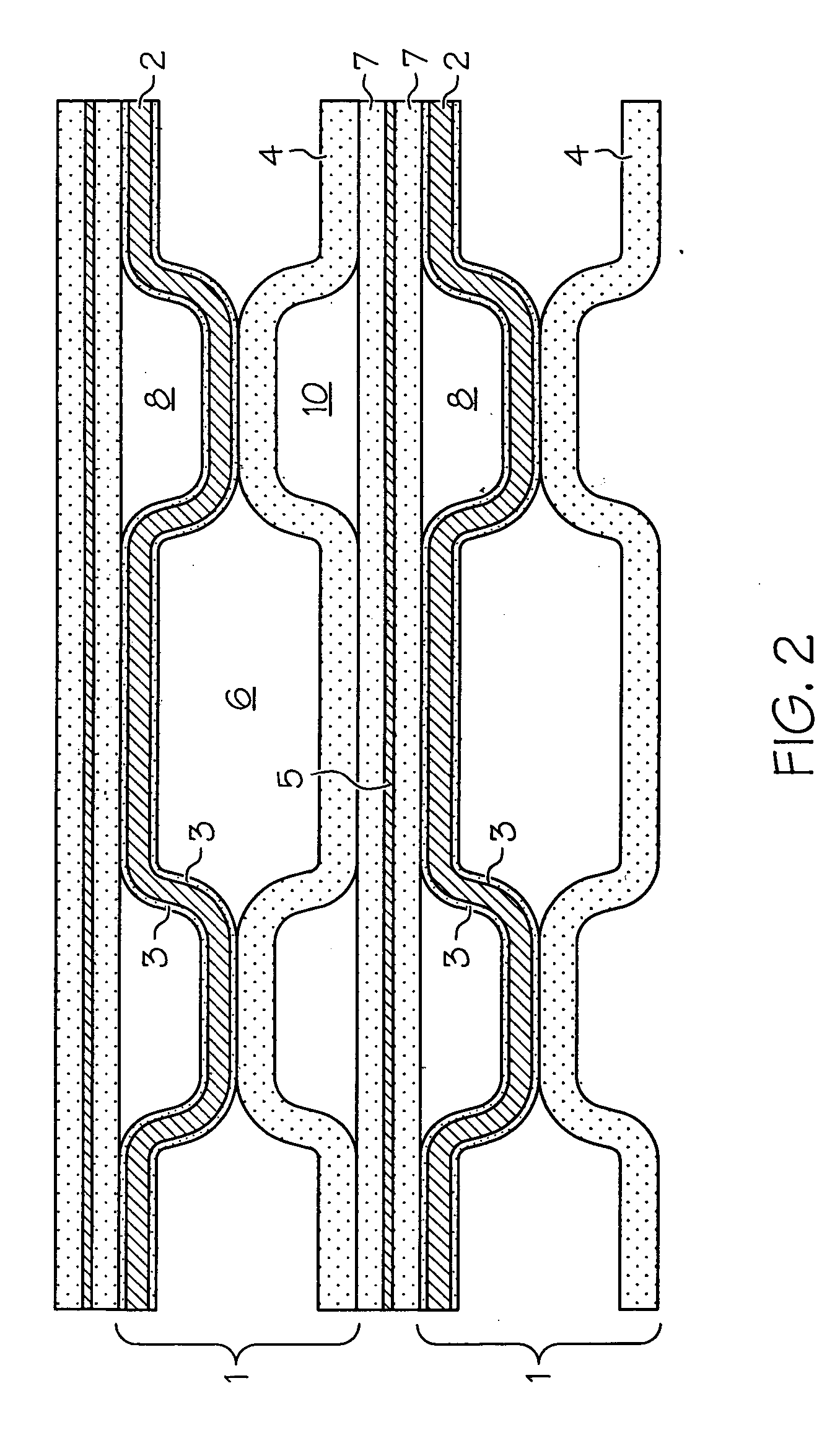
[0018] In accordance with one embodiment of the present invention, a hybrid bipolar plate assembly 1 is provided, which assembly 1 can be used in an electrochemical conversion assembly (e.g., fuel cell). The assembly 1 comprises a metallic anode plate 2, a composite cathode plate 4, and a first layer 3 positioned between the metallic anode plate 2 and the composite cathode plate 4, which hybrid bipolar plate assembly 1 is illustrated in FIGS. 1, 2 and 3. The first layer 3 can comprise at least one of gold, silver and alloys of each. By employing the useful properties of both metals and composites, the hybrid bipolar plate assembly 1 addresses many of the drawbacks typically encountered with conventional bipolar plates that are entirely comprised of either metallic or composite materials. More particularly, the hybrid bipolar plate assembly 1 of the present invention takes advantage of the greater mechanical strength and lower thickness provided by metallic plates, and the improved w...


PUM

PropertyMeasurementUnit
thicknessaaaaaaaaaa
thicknessaaaaaaaaaa
thickaaaaaaaaaa

Abstract

A hybrid bipolar plate assembly comprises a metallic anode plate, a polymeric composite cathode plate, and a metal layer positioned between the metallic anode plate and the composite cathode plate. The metallic anode and composite cathode plates can further comprise an adhesive sealant applied around the outer perimeter to prevent leaking of coolant. The assembly can be incorporated into a device comprising a fuel cell. Further, the device can define structure defining a vehicle powered by the fuel cell.

Description

BACKGROUND OF THE INVENTION [0001] Fuel cell systems with bipolar plates are known. SUMMARY OF THE INVENTION [0002] Fuel cells such as, for example, proton exchange membrane (PEM) fuel cells, produce electrical energy through hydrogen oxidation and oxygen reduction. The byproduct of these catalytic reactions is water. A typical cell comprises a polymer membrane (e.g., proton exchange membrane) that is positioned interjacent a pair of gas diffusion media and catalyst layers. A cathode plate and an anode plate are positioned at the outermost sides adjacent the gas diffusion media layers, and the preceding components are tightly compressed to form the cell unit. [0003] The voltage provided by a single cell unit is typically too small for useful application. Accordingly, a plurality of cells are typically arranged and connected consecutively in a “stack” to increase the electrical output of the electrochemical conversion assembly or fuel cell. In this arrangement, two adjacent cell unit...

Claims


Application Information

Patent Timeline
03 Nov 2005
Publication
US20050244700A1
IPC
H01M2/08; H01M8/02; H01M8/10
CPC
H01M8/0206; H01M8/021; H01M8/0213; H01M8/0221; H01M8/0226; H01M8/0228; Y02E60/521; H01M8/026
Inventors
ABD ELHAMID, MAHMOUD H.; BLUNK, RICHARD H.