Flexible dimension crown shells

a flexible, crown shell technology, applied in the field of temporary and provisional dental crowns and bridges, can solve the problems of poor fit of conventional shells, difficult to get good proximal contact with adjacent teeth, and poor fit of margins, etc., to achieve high cost, high durability, and fast production

Inactive Publication Date: 2005-11-03
CROWNBEAV
View PDF21 Cites 10 Cited by
  • Summary
  • Abstract
  • Description
  • Claims
  • Application Information

AI Technical Summary

Benefits of technology

[0025] Long-term provisional crowns made according to this invention provide an alternative to high cost crowns, offering benefits to patients, dentists, and insurance companies. Both temporary and long-term provisional crowns made according to this invention are accurate, can be made very fast, and are more durable than most of the prior art. Crowns made using the long-term provisional shells should last 5-7 years or longer. Crowns made using the temporary shells (having slightly thinner walls than in provisional shells) last from 3-4 months up to about 1 year. Crowns made according to this invention are also simpler and easier to install than molded crowns and are mu...

Problems solved by technology

Using prefabricated forms, as in the first technique, for example, is fast and simple, but the fit of the conventional shell is not very good.
The margins, in particular, do not fit well.
Specifically, it is hard to get good proximal contact to adjacent teeth, and the contours and occlusion are not always good.
Unfortunately, this attempted solution is expensive in terms of materials and also in terms of the time required for the dentist to pick the right shell.
Such trimming and fitting is time-consuming for the dentist and the patient.
The second technique gives good contours and bite accuracy, but making an impression is time-consuming.
Furthermore, neither the strength nor the durability of temporary crowns produced by this technique are very good.
Furthermore, the impression cannot be made if the patient's tooth is already broken when initially treated.
It, too, however,...

Method used


Image

  • Flexible dimension crown shells
  • Flexible dimension crown shells
  • Flexible dimension crown shells

Examples


first embodiment

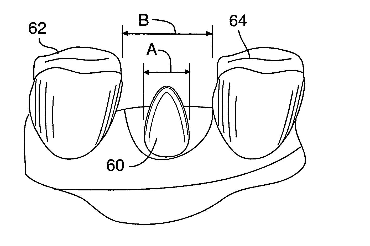
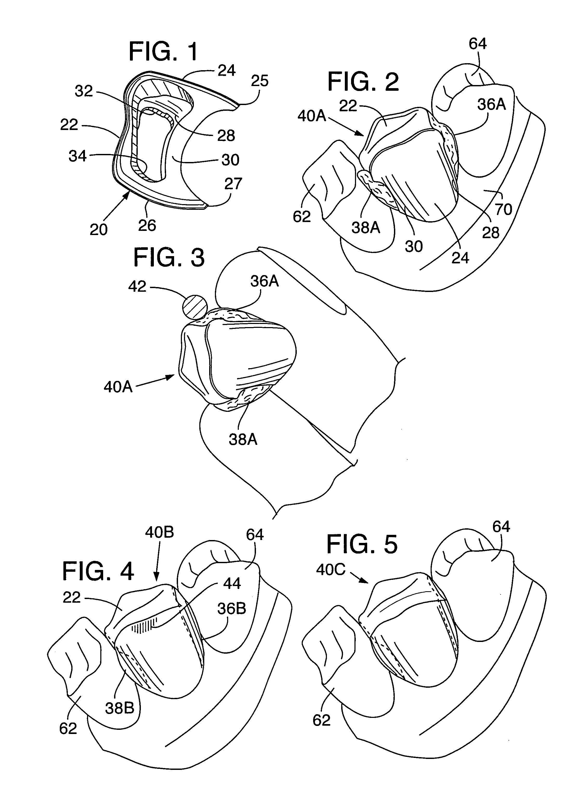
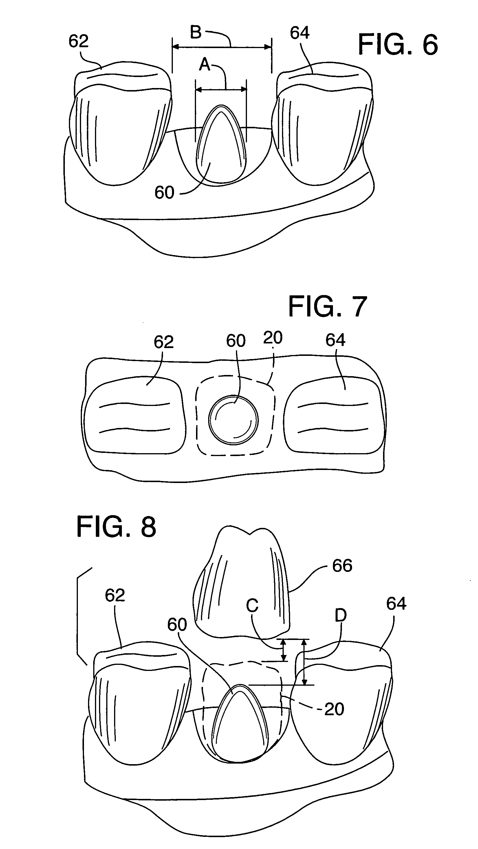
[0047]FIGS. 1-5 illustrate the basic concept of the present invention in a first embodiment with respect to a bicuspid crown. Although these figures are specifically directed toward bicuspid crowns, the following description applies equally to crowns for molars. Molar crowns are more specifically described in connection with subsequent figures.

[0048]FIG. 1 is a side elevation view of a shell 20 for making a temporary or long-term provisional bicuspid crown. The shell 20 is preferably integrally molded of polycarbonate material but can be made of other polymeric materials and can be machined rather than molded. The shell 20 has a top wall 22 that defines an occlusal surface; a buccal sidewall 24; and a lingual sidewall 26 spaced from the buccal sidewall. The buccal sidewall 24 can include a detachable tab (not shown) for handling the shell during making of the crown. Opposite mesio-distal sidewalls 28, 30, are connected to the top wall 22 and the buccal and lingual sidewalls 24, 26, ...

second embodiment

[0062]FIGS. 9-13 show various views of a bicuspid shell 120 according to the invention. The general arrangement, materials, and procedure for making temporary and provisional crowns using shell 120 can be the same as those described above for shell 20 (see FIG. 1). The preferred sizing and method of fitting are described below with reference to FIGS. 33-44. The parts of shell 120 that correspond to parts in shell 20 are denoted by the same reference numerals, incremented by 100. Accordingly, shell 120 has an occlusal (or top) wall 122, buccal and lingual sidewalls 124, 126 with gingival margins 125, 127, respectively, and proximal (mesio-distal) sidewalls 128, 130.

[0063] Unlike the mesio-distal windows 32, 34 of the shell 20 of the first embodiment, however, which are bounded along the gingival margins of the mesio-distal sidewalls, the mesio-distal windows 132, 134 of the shell 120 in this embodiment have a generally U-shape and unbounded along the gingival margins of the proximal ...

third embodiment

[0078]FIGS. 17-24 show a bicuspid shell 320 and a molar shell 420 according to the invention. Structural elements and features in common with the previously-described embodiments are indicated by like reference numerals incremented by 300 and 400 for the bicuspid and molar shells, respectively. The proximal sidewalls can also be recessed or indented (not shown) as shown and described with reference to FIGS. 9-16 and FIGS. 25-32.

[0079] There are several differences between the bicuspid and molar shells 320, 420 of this embodiment and the shells of the previous embodiments. First, the occlusal walls 322, 422 each have a single cross-shaped occlusal window 353, 453, best seen in FIGS. 17 and 21. This window arrangement provides somewhat more window area for resin extrusion onto the top walls 322, 422 as compared to the occlusal windows 150, 152 of the second embodiment, but still provides support for the filler in the finished crown. Second, the gingival margins of the shells are inter...


PUM


Abstract

A temporary or long-term provisional crown includes a shell having a top wall defining an occlusal surface, a buccal sidewall, a lingual sidewall, and opposite mesio-distal sidewalls, connected to the top wall and buccal and lingual sidewalls and spaced apart to define a central cavity to fit over a prepared tooth. A quantity of resin is disposed in the central cavity of the shell and is preferably shaped to conform to a prepared tooth. Two U-shaped windows arranged in one or both of the mesio-distal sidewalls permit resin to protrude mesio-distally from the cavity to contact an adjacent tooth. A window in the top wall extends mesio-distally to permit resin to extrude on to the occlusal surface. The occlusal window can be hourglass-shaped.

Description

RELATED APPLICATION DATA [0001] This application is a continuation-in-part of co-pending U.S. patent application Ser. No. 10 / 238,976, filed Sep. 9, 2002, which is a continuation-in-part of co-pending U.S. patent application Ser. No. 09 / 808,700, filed Mar. 14, 2001, now U.S. Pat. No. 6,447,296, which claimed priority from U.S. provisional application Ser. No. 60 / 190,127, filed Mar. 16, 2000, and which is a continuation-in-part of U.S. Ser. No. 09 / 484,944, filed Jan. 18, 2000, now U.S. Pat. No. 6,257,892B1, which claimed priority from U.S. provisional application Ser. No. 60 / 131,817, filed Apr. 29, 1999, and which is a continuation-in-part of co-pending U.S. Ser. No. 09 / 178,023, filed Oct. 23, 1998, now U.S. Pat. No. 6,068,481, which claimed priority from U.S. provisional application Ser. No. 60 / 063,410, filed Oct. 28, 1997, all incorporated herein by reference and all commonly assigned.BACKGROUND OF THE INVENTION [0002] This invention relates generally to temporary and provisional de...

Claims


Application Information

Patent Timeline
IPC IPC(8): A61C3/00A61C5/08A61C5/77A61C13/00
CPCA61C5/08A61C13/0003A61C5/10A61C5/70A61C5/77
Inventor WORTHINGTON, MARK L.
Owner CROWNBEAV
Why Eureka
Try Eureka