Catheter systems having flow restrictors

a technology of flow restrictors and catheters, applied in the field of implantable medical devices, can solve the problems of increased cost, patient invasiveness, increased complexity inherent in such dual systems, and achieve the effect of reducing the frequency of replenishmen

Active Publication Date: 2005-11-03
MEDTRONIC INC
View PDF37 Cites 44 Cited by
  • Summary
  • Abstract
  • Description
  • Claims
  • Application Information

AI Technical Summary

Benefits of technology

[0015] The fluids delivered using the present invention preferably contain one or more drugs. A drug of the present invention may include a therapeutic substance. Other substances may or may not be intended to have a therapeutic effect and are not easily classified, such as, e.g., saline solution, fluoroscopy agents, disease diagnostic agents, etc. Unless otherwise noted in the following paragraphs, the term “drug” as used herein may include any therapeutic, diagnostic, or other substance that is delivered using the implantable medical devices of the present invention.
[0016] Therapeutic substances delivered using the present invention may preferably be intended to have a therapeutic effect such as pharmaceutical compositions, genetic materials, biologics, and other substances. Pharmaceutical compositions are

Problems solved by technology

However, duplicate systems result in not only increased costs and patient invasiveness (as compared

Method used


Image

  • Catheter systems having flow restrictors
  • Catheter systems having flow restrictors
  • Catheter systems having flow restrictors

Examples


example

[0084] The following example is provided to illustrate exemplary embodiments of the invention.

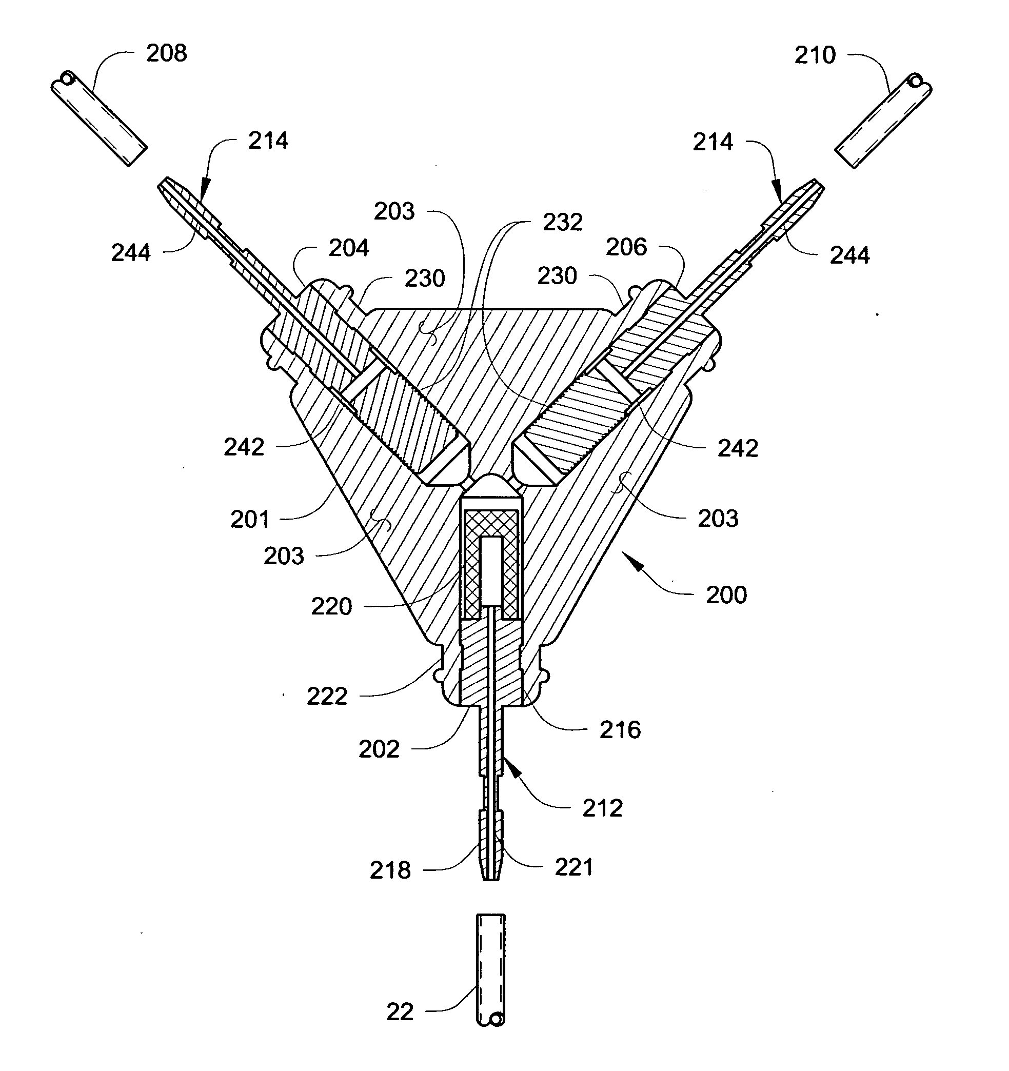
[0085] A Medtronic SYNCHROMED II pump was used to infuse a saline solution at a rate of about 300 microliters / day (μL / day)—about 150 μL / day per side (left and right)—via a catheter branching connector substantially similar to that illustrated in FIGS. 3A and 3B.

[0086] The connector incorporated a filter (see, e.g., filter 220) having a 5 micron rating. An outlet fitting (see, e.g., fitting 214 in FIG. 5) incorporating a flow restrictor (see e.g., flow restrictor 232) was also provided. The restrictor included a helical groove (see, e.g., groove 234) formed on a uniform cylindrical portion of the outlet fitting. The flow restrictor had a nominal diameter of about 0.072 inches (about 1.8 mm) and a length of about 0.14 inches (about 3.6 mm). The groove had a nominal depth of about 0.0012 inches (about 0.03 mm), and a pitch of about 250 threads / inch (about 10 threads per mm).

[0087] The pump,...


PUM


Abstract

Catheter systems including one or more flow restrictors are disclosed. The catheter systems may include two or more delivery branches. The delivery branches may be connected to a supply catheter section using a branching catheter connector that may include one or more flow restrictors. The flow restrictors may include a restrictor body located within a lumen with a channel located between the restrictor body and interior surface of the lumen, the channel restricting flow through the lumen past the flow restrictor. The channel may be defined by a groove formed in the restrictor body and/or the interior surface of the lumen. Methods of providing pressure relief by flowing fluid past a flow restrictor are also disclosed.

Description

RELATED APPLICATION [0001] This application claims the benefit of U.S. Provisional Application No. 60 / 564,473, titled CATHETER SYSTEM HAVING FLOW RESTRICTION, AND DIAGNOSTIC SYSTEM FOR USE WITH SAME, filed Apr. 22, 2004, which is hereby incorporated by reference in its entirety.TECHNICAL FIELD [0002] The present invention relates generally to implantable medical devices and, more particularly, to flow restrictors in medical catheters and branching catheter connectors incorporating one or more flow restrictors. BACKGROUND [0003] Implantable infusion systems are used to provide programmable long-term delivery of a therapeutic agent, e.g., infusate drug, to a target site such as the brain or the spinal canal or epidural space. These systems typically include a pump implanted at a remote location, e.g., within the abdominal or chest cavity, and a catheter tunneled from the pump to the target site. A drug may be delivered from a reservoir in the pump to the target site via the catheter. ...

Claims


Application Information

Patent Timeline
IPC IPC(8): A61M1/00A61M5/142A61M5/168A61M25/00A61M27/00A61M31/00A61M39/10A61M39/22F16K1/40F16K47/12G01F1/68
CPCA61M5/14276A61M2206/16A61M25/00A61M25/0021A61M25/0029A61M25/003A61M25/0043A61M25/0068A61M25/0071A61M25/0075A61M27/006A61M2025/0073A61M2039/1005A61M2205/15A61M5/16813
Inventor OLSEN, JAMES M.MORRIS, MARY M.HEGLAND, MICHAELBLANCO, JUSTIN A.
Owner MEDTRONIC INC
Why Eureka
Try Eureka