Initial setting method of refrigerant entrance/exit (inlet/outlet) pipe onto header pipe for heat exchanger

Inactive Publication Date: 2005-11-10
MODINE KOREA
View PDF1 Cites 5 Cited by
  • Summary
  • Abstract
  • Description
  • Claims
  • Application Information

AI Technical Summary

Benefits of technology

[0006] The invention has been developed to improve the existing problems. The invention's purpose is to provide an improved in

Problems solved by technology

During this brazing process, the setting condition of the header pipe's (100) refrigerant inlet/outlet pipe (20

Method used


Image

  • Initial setting method of refrigerant entrance/exit (inlet/outlet) pipe onto header pipe for heat exchanger
  • Initial setting method of refrigerant entrance/exit (inlet/outlet) pipe onto header pipe for heat exchanger
  • Initial setting method of refrigerant entrance/exit (inlet/outlet) pipe onto header pipe for heat exchanger

Examples


Example

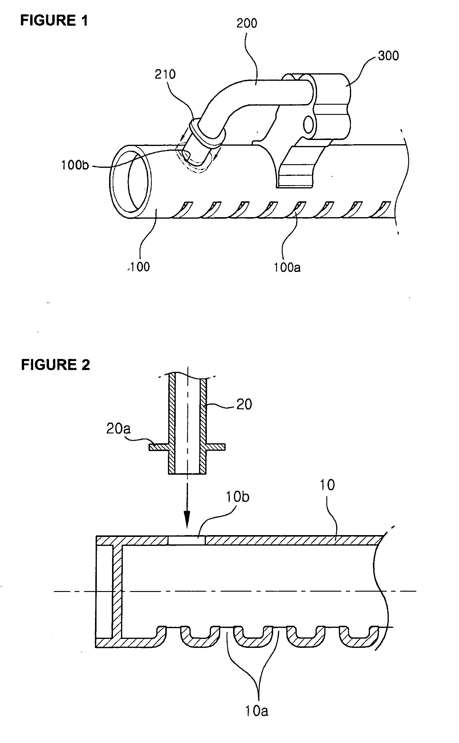
[0014] First, as shown in FIG. 2, the refrigerant tube connection holes (10a) are made at one side of the header pipe (10), and an assembly hole is made at the opposite side of these connection holes (10a) for the refrigerant inlet / outlet pipe (20) assembly. In addition, at the upper end of refrigerant inlet / outlet pipe (20), a bead (20a) is made by following the header pipe's (10) curvature. It is desirable to make this bead (20a) at the same time that the refrigerant inlet / outlet pipe (20) is made, and this bead (20a) replaces the previously used washer (210).

[0015] Then, as in FIG. 1, an end part of the refrigerant inlet / outlet pipe (20) is inserted onto the header pipe (10)'s refrigerant inlet / outlet pipe assembly hole (10b). At this time, the bead (20a) at the refrigerant inlet / outlet pipe (20) should be closely conforming to the exterior surface of header pipe (10).

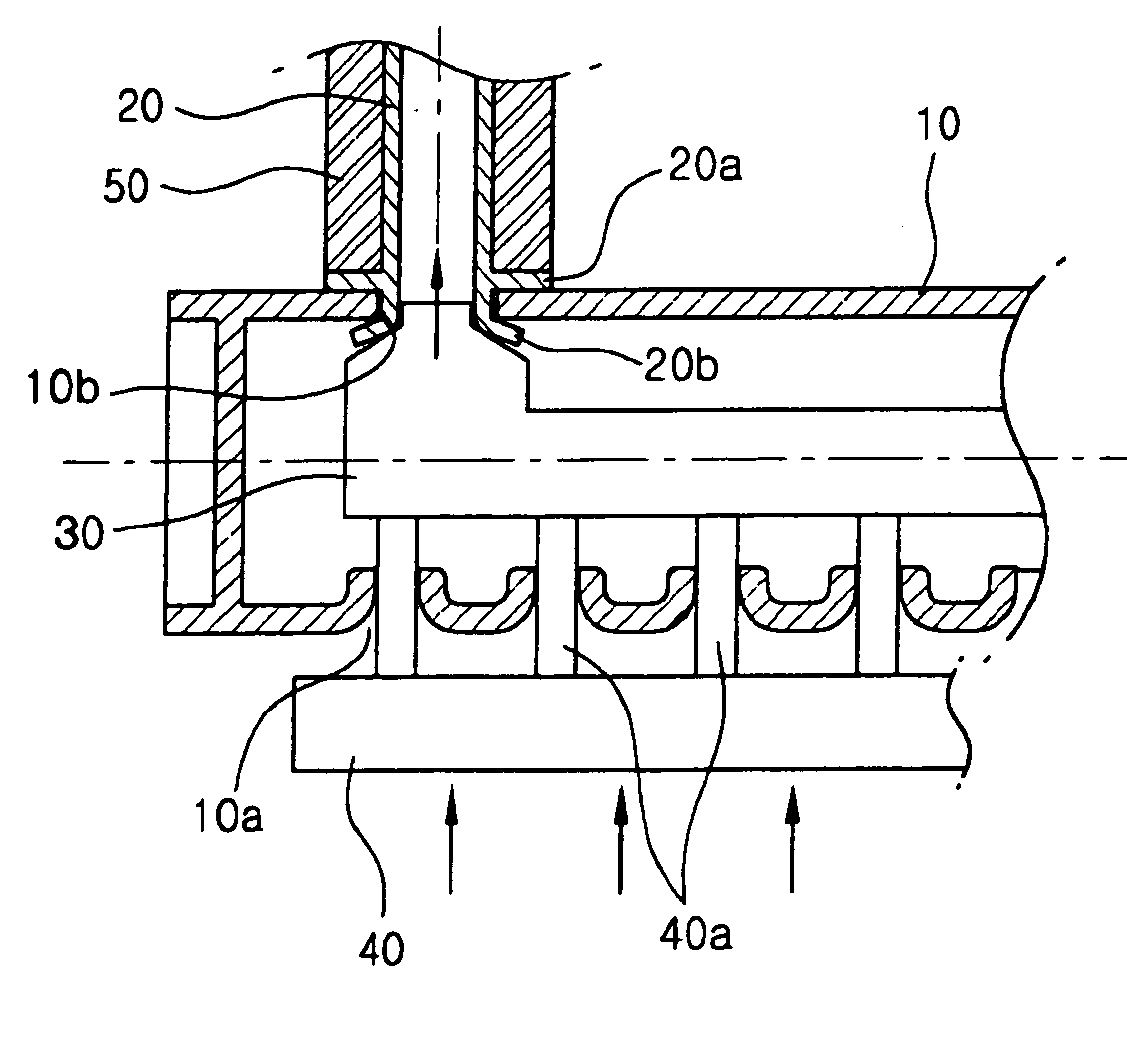
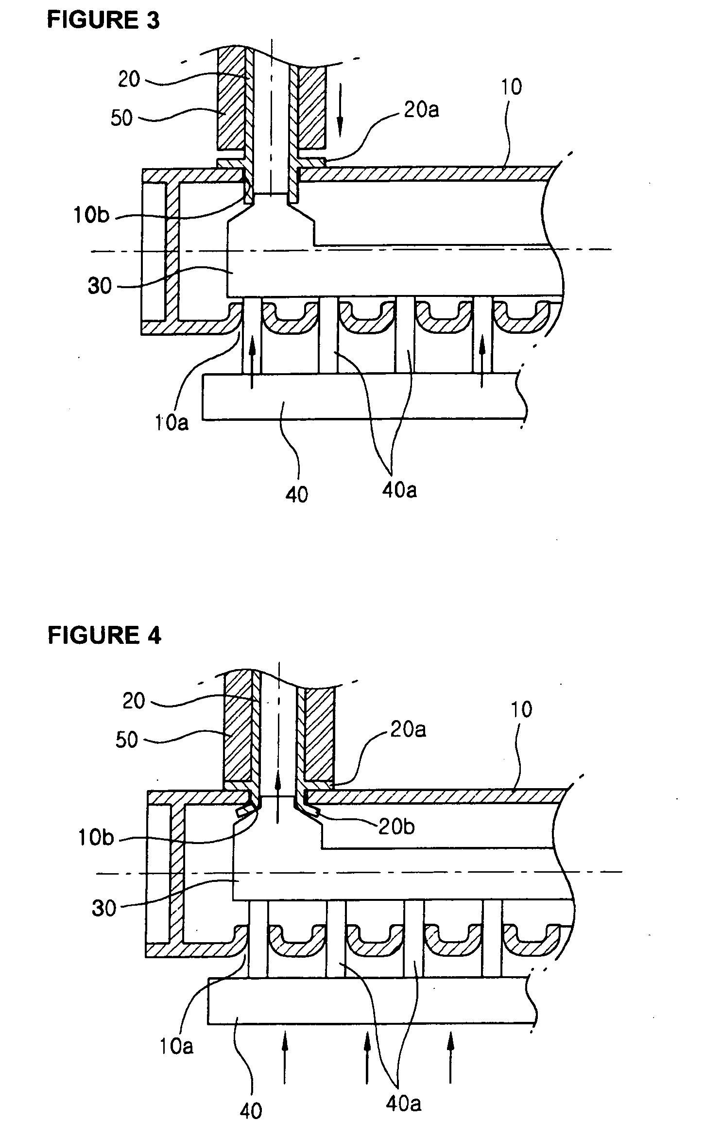
[0016] Next, as shown in FIG. 3, an expanding tool (30) is inserted into the header pipe (10). The front of the...


PUM


Abstract

The present invention relates to a method for the initial setting of a refrigerant inlet/outlet pipe onto a header pipe for a heat exchanger to improve the initial setting property and the brazing junction property of the refrigerant inlet/outlet pipe with respect to the header pipe. The method utilizes a support board that is installed through the refrigerant tube connection holes to support and press a pipe expanding tool which deforms an end of the refrigerant inlet/outlet pipe on an interior side of the header pipe.

Description

FIELD OF THE INVENTION [0001] The present invention relates to a technology in the air conditioner heat exchanger field. In particular, it relates to the initial setting before the brazing of the refrigerant inlet / outlet pipe onto a header pipe which is used for the heat exchanger and refrigerant tube connection. BACKGROUND OF THE INVENTION [0002] A vehicle air conditioner heat exchanger, such as a condenser, consists of many refrigerant tubes so that the refrigerant which is a medium for a heat exchange can perform on the inside of the heat exchanger effectively with the outside air. These refrigerant tubes' end parts are connected by the header pipe which forms the flow route for the flow. [0003] One side of the header pipe is assembled with a refrigerant inlet / outlet pipe for the entrance and exit of the refrigerant. Generally, the complete connection of the header pipe and the refrigerant inlet / outlet (inlet or outlet) pipe is accomplished when the refrigerant inlet / outlet pipe ...

Claims


Application Information

Patent Timeline
IPC IPC(8): B21D39/06B21D53/06F28F9/02B23P11/00B23P15/26F28D1/00F28D1/04F28F9/00F28F9/04
CPCB21D39/06B21D41/02F28F9/002Y10T29/4935Y10T29/49361Y10T29/4992Y10T29/49915F28F9/0246E04C3/36B27K3/02
Inventor MIN, KYUNG GEUN
Owner MODINE KOREA
Why Eureka
Try Eureka