Encoder system

a technology of encoder system and encoder body, which is applied in the direction of mechanical measurement arrangement, instruments, and mechanical means, can solve the problems of high mounting precision, high installation cost, and laborious installation process of current encoder system, and achieve the effect of easy installation of encoder system, accurate and inexpensiv

Inactive Publication Date: 2005-11-10
UNIVERSAL INSTR
View PDF43 Cites 10 Cited by
  • Summary
  • Abstract
  • Description
  • Claims
  • Application Information

AI Technical Summary

Benefits of technology

[0014] The present invention advantageously provides a structure and associated method for an inexpensive, accurate, and easy to install an encoder system for use with a positioning system.

Problems solved by technology

However, the current encoder systems are typically very expensive, especially when there is a long axis of travel.
In addition, they are very sensitive to positional misalignment between the reading device and the precision scale which causes not only a labor intensive installation process, but requires high precision machining of the mounting surfaces to which the system mounts.

Method used


Image

  • Encoder system
  • Encoder system
  • Encoder system

Examples


Embodiment Construction

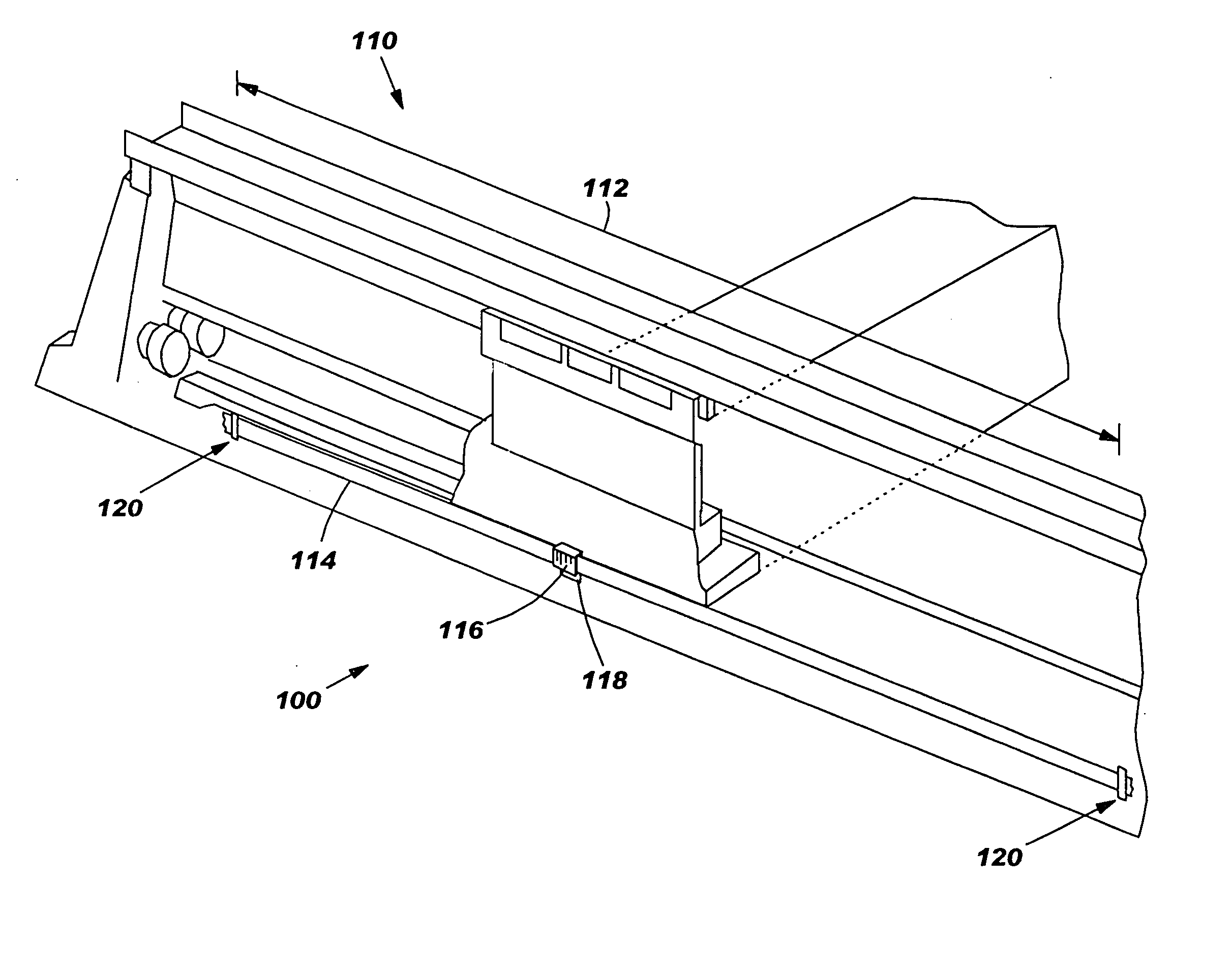
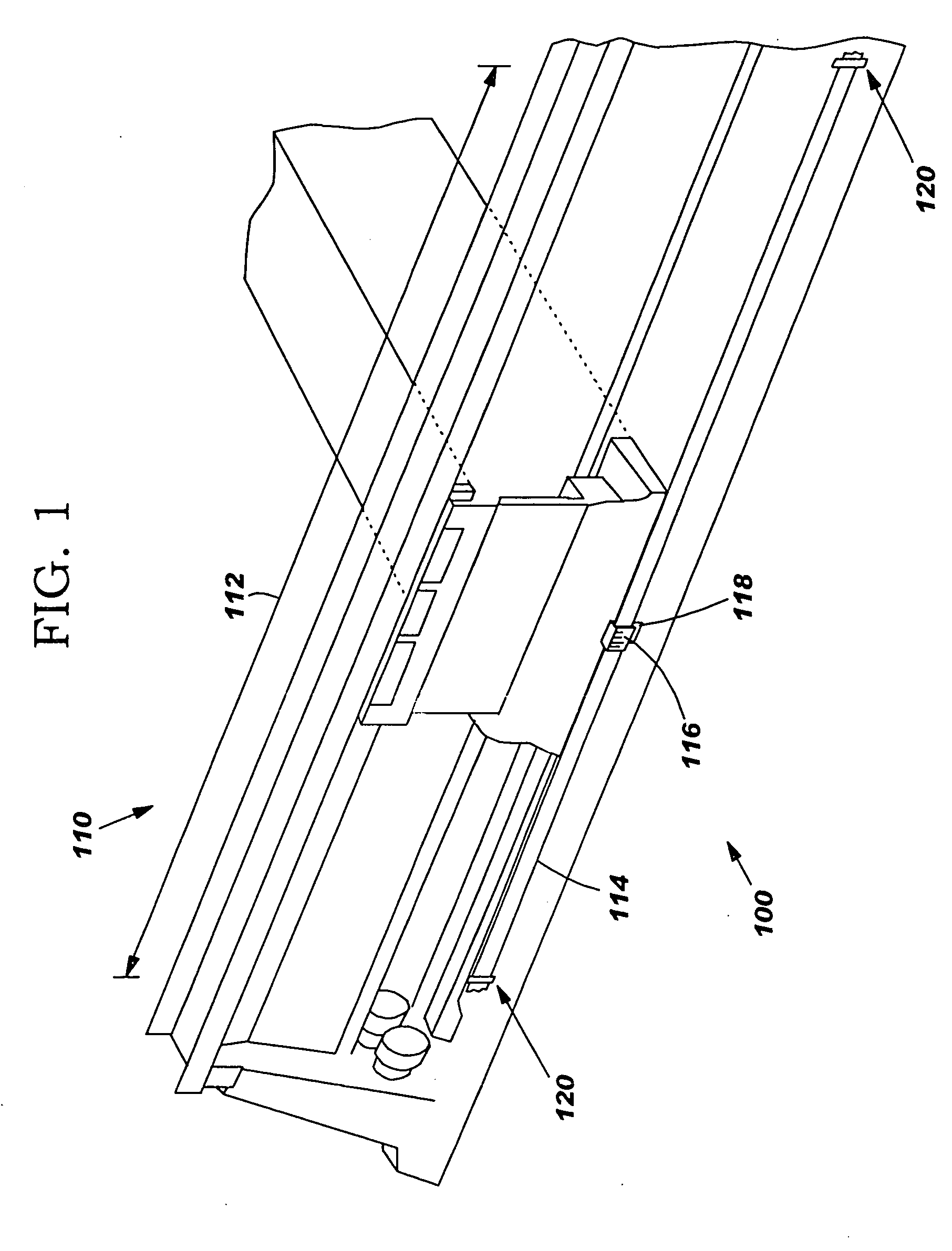
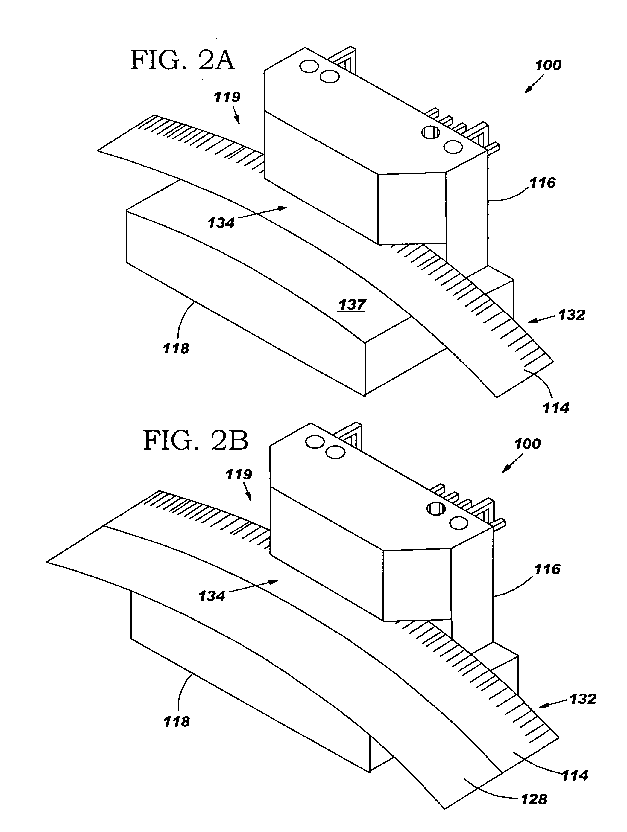
[0027]FIG. 1 illustrates a perspective view of an encoder system 100 mounted within a positioning system 110, in accordance with embodiments of the present invention. The encoder system controls a spatial position (e.g., in an X, Y, or Z plane) of the positioning system 110. The encoder system comprises, an encoder tape 114, a read head 116, and a shoe 118. The read head 116 and the shoe 118 in combination form an encoder structure 119. Ends 120 of the encoder tape 114 are secured on either side of the axis of travel 112 of the read head 116 and the shoe 118. The encoder tape 114 has lines (e.g., see lines 132 in FIG. 2A), features, markings, or aperture type features (e.g., openings, holes, slots, etc) on it such as can be read by the read head 116. The encoder tape 114 may be any encoder tape known to a person of ordinary skill in the art including, inter alia, a clear plastic encoder tape with lines, markings, or features (as shown in FIGS. 2-3), a non-clear encoder tape (e.g., o...


PUM


Abstract

A structure and associated method to accurately read an encoder tape in an encoder system. The encoder system comprises, a read head, a shoe structure adjacent the read head, and an encoder tape. The encoder tape is adapted to be read by the read head. The shoe structure is adapted to locally support the encoder tape and locally dampen a vibration of the encoder tape as the encoder tape is read by the read head.

Description

BACKGROUND OF THE INVENTION [0001] 1. Technical Field [0002] This invention relates to encoder systems used in positioning systems. [0003] 2. Related Art [0004] Current encoder systems used for positioning systems typically use precision scales and reading devices. However, the current encoder systems are typically very expensive, especially when there is a long axis of travel. In addition, they are very sensitive to positional misalignment between the reading device and the precision scale which causes not only a labor intensive installation process, but requires high precision machining of the mounting surfaces to which the system mounts. Therefore there is a need for an inexpensive, accurate, and easy to install an encoder system for use with a positioning system. SUMMARY OF THE INVENTION [0005] The present invention provides an encoder system comprising: [0006] a read head; [0007] a shoe structure adjacent the read head; and [0008] an encoder tape adapted to be read by the read ...

Claims


Application Information

Patent Timeline
Patent Type & Authority Applications(United States)
IPC IPC(8): G01D5/347G01D11/30G01D21/00
CPCG01D5/24442G01D5/34707G01D11/30G01D11/10G01D5/34753G01D5/12G01D5/00G01D21/00
Inventor SNYDER, MICHAEL D.GIESKES, KOEN A.
Owner UNIVERSAL INSTR
Why Eureka
Try Eureka