
Ignition arrangement for stacked projectiles

a technology of stacked projectiles and stacked barrels, which is applied in the direction of electric fuzes, ammunition fuzes, lighting and heating apparatus, etc., can solve the problems of adding the construction complexity of both individual barrel assemblies with stacked projectiles and weapons pods, and achieve the effect of convenient insertion of fuses

Inactive Publication Date: 2005-11-10
DEFENDTEX
View PDF5 Cites 10 Cited by
  • Summary
  • Abstract
  • Description
  • Claims
  • Application Information

AI Technical Summary

Benefits of technology

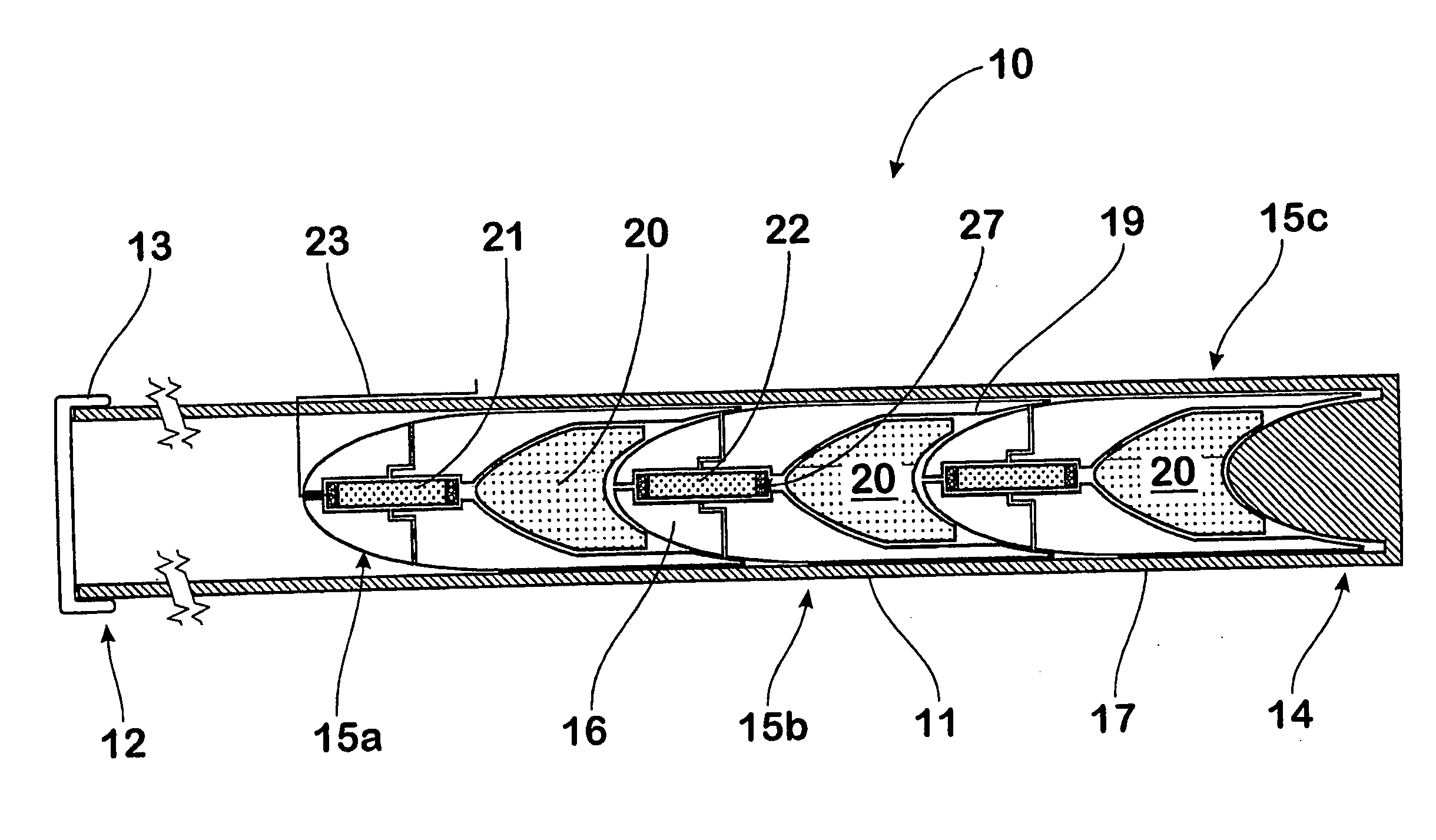
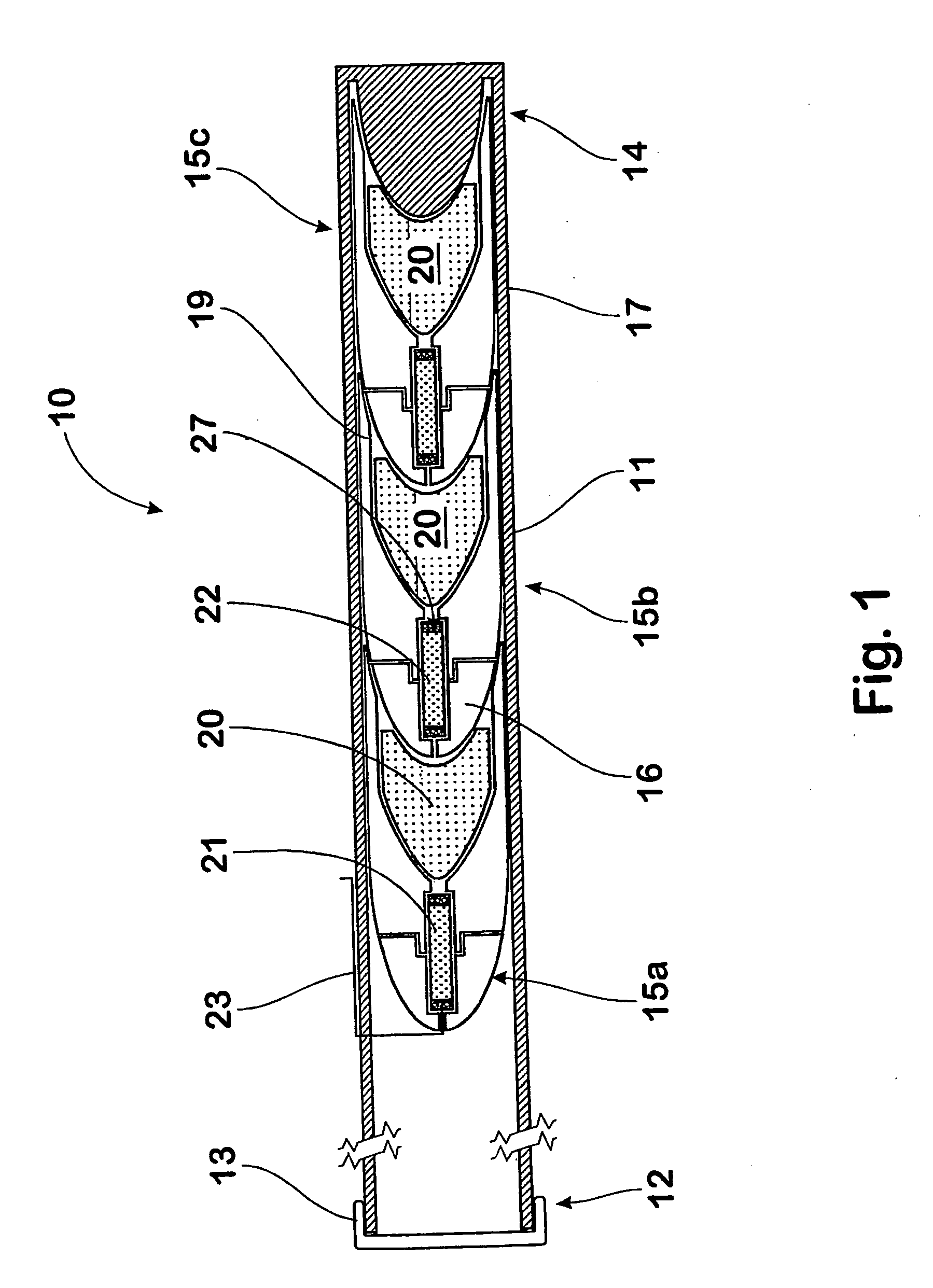
[0011] The forward communication of the cavity allows burning of said fuse to be triggered by combustion of a forward propellant charge associated with the immediately preceding projectile in the axial stack of projectiles during discharge of said preceding projectile.
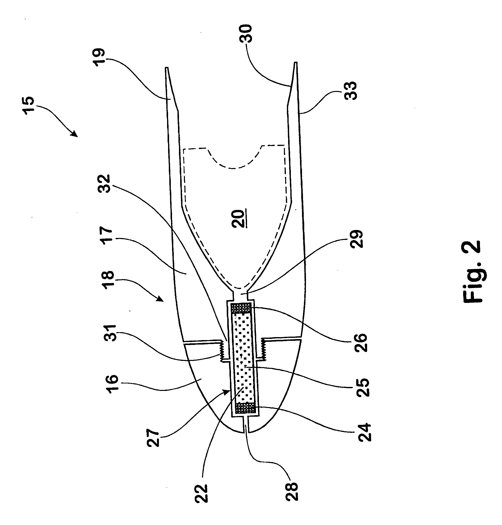
[0016] The fuse material of the intermediate section may also provide a sealing function, in that burnt fuse material can provide at least a partial seal within the cavity and / or the first aperture.
[0022] The projectile body is desirably composed of at least two separate components to facilitate convenient insertion of the fuse into the cavity, which components are suitably fixed together subsequent to fuse insertion thereby retaining the fuse within the projectile body. If required, the projectile components may be releasably coupled together.

Problems solved by technology

This added to construction complexity of both individual barrel assemblies with stacked projectiles and to weapons pods incorporating clusters of barrel assemblies.

Method used


Image

  • Ignition arrangement for stacked projectiles
  • Ignition arrangement for stacked projectiles
  • Ignition arrangement for stacked projectiles

Examples


first embodiment

[0052] In another embodiment of the invention, the composition of the intermediate material is selected, such that when burnt, the residual melted material (perhaps a filler) provides a sealing action in the front aperture 28 and / or across the cavity 27 to further mitigate pressure loss. Alternatively, the fuse may be provided with a housing which melts and obturates the cavity 27 during or consequent to fuse burning. The constrictions in the front and rear of the fuse chamber in the projectile of the first embodiment are designed to aid in this procedure.

[0053] The front and rear sections 24, 26 capping the ends of the fuse 22 are provided because it is believed that the fuse material suited to controlled burning at a stable rate may be unable to reliably initiate combustion of the propellant charges 20 and vice-versa. Where a suitably synergistic fuse material and propellant can be specified, the front and rear sections capping the fuse may not be required. In some embodiments, th...

second embodiment

[0055] A fuse 40 for the ignition arrangement of the second embodiment has a body 41 adapted for insertion into the projectile bore 37 is illustrated in FIG. 3. The fuse body 41 is in the form of a sleeve, having an external screw-thread 42 and an internal cavity 43 containing fuse material (not shown). A slot 44 is provided across an end face of the fuse body 41 to facilitate engagement by a tool for insertion of the fuse 40 into the projectile body 36.

[0056] In further contrast to the fuse of the first embodiment, neither the cavity provided in the projectile body 36, nor the internal cavity 43 in the fuse 40 are provided with restricted apertures or similar end constrictions. The fuse material is pressed into the internal cavity of the fuse and forms a stable compacted mass. It will be appreciated that other embodiments of the invention may employ constrictions in either or both of the fuse body 41 and / or the projectile body 36, as required.

[0057] The illustrated fuse 40 is desi...


PUM


Abstract

An ignition arrangement for a barrel assembly (10) including a barrel (11) having a plurality of projectiles (15a, 15b, 15c) axially stacked within the barrel (11) together with respective propellant charges (20) for propelling the projectiles sequentially from the barrel, said ignition arrangement including a fuse (21, 22) disposed in a cavity (27) provided in a body (18) of each projectile, wherein the cavity (27) communicates both forwardly (28) and rearwardly (29) of the projectile body (18); whereby in use, said fuse (21) burns at a controlled rate in the cavity (27) and causes ignition of the propellant charge (20) associated with said projectile (15a), which in turn ignites the next following fuse (22) associated with a trailing projectile (15b).

Description

BACKGROUND OF THE INVENTION [0001] 1. Field of the Invention [0002] The present invention relates to ignition arrangements for munitions and firearms. In particular, although not exclusively, the invention relates to fusing arrangements for igniting propellant charges associated with respective projectiles stacked axially within a barrel. The invention also relates to a method of igniting such propellant charges for stacked projectiles. [0003] 2. Discussion of the Background Art [0004] There is disclosed in the prior art several proposals for igniting propellant charges associated with projectiles stacked axially within a barrel. In some of these proposals, electrical conductors are required for carrying ignition signals to individual propellant charges for each projectile in a barrel. This added to construction complexity of both individual barrel assemblies with stacked projectiles and to weapons pods incorporating clusters of barrel assemblies. [0005] Whilst electronic ignition a...

Claims


Application Information

Patent Timeline
IPC IPC(8): F41A19/58F42B5/03
CPCF42B5/035F41A19/58
Inventor O'DWYER, SEAN PATRICK
Owner DEFENDTEX
Learn More