Grafting tool

a grafting tool and tool body technology, applied in the field of grafting tools, can solve problems such as difficulty in mateing the two, and achieve the effect of precise cutting

Inactive Publication Date: 2005-11-10
SOWINSKI THOMAS
View PDF28 Cites 7 Cited by
  • Summary
  • Abstract
  • Description
  • Claims
  • Application Information

AI Technical Summary

Benefits of technology

[0008] This invention, advantageously, provides a handheld tool and method which enables the user to make precise cuts that ensure that diagonal cuts on two different stems will mate correctly. This invention, likewise, enables cleft grafts in that the angle of the cut on the scion remains constant. For example, this grafting tool ensures an exact cut that exposes an inch to an inch and one-half (1″ to 1.5″) of a diagonal cut on each piece to be mated.

Problems solved by technology

In the past it has been difficult to mate the two because of uneven cuts owing to too severe of an angle or not enough of an angle.
In either of these circumstances, poor contact between the two cambium layers of the stock to be mated results in poor results.

Method used


Image

  • Grafting tool
  • Grafting tool
  • Grafting tool

Examples


Embodiment Construction

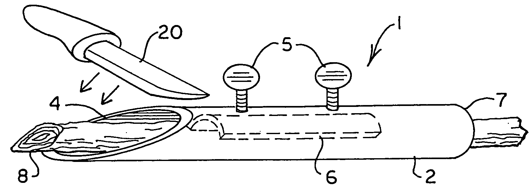
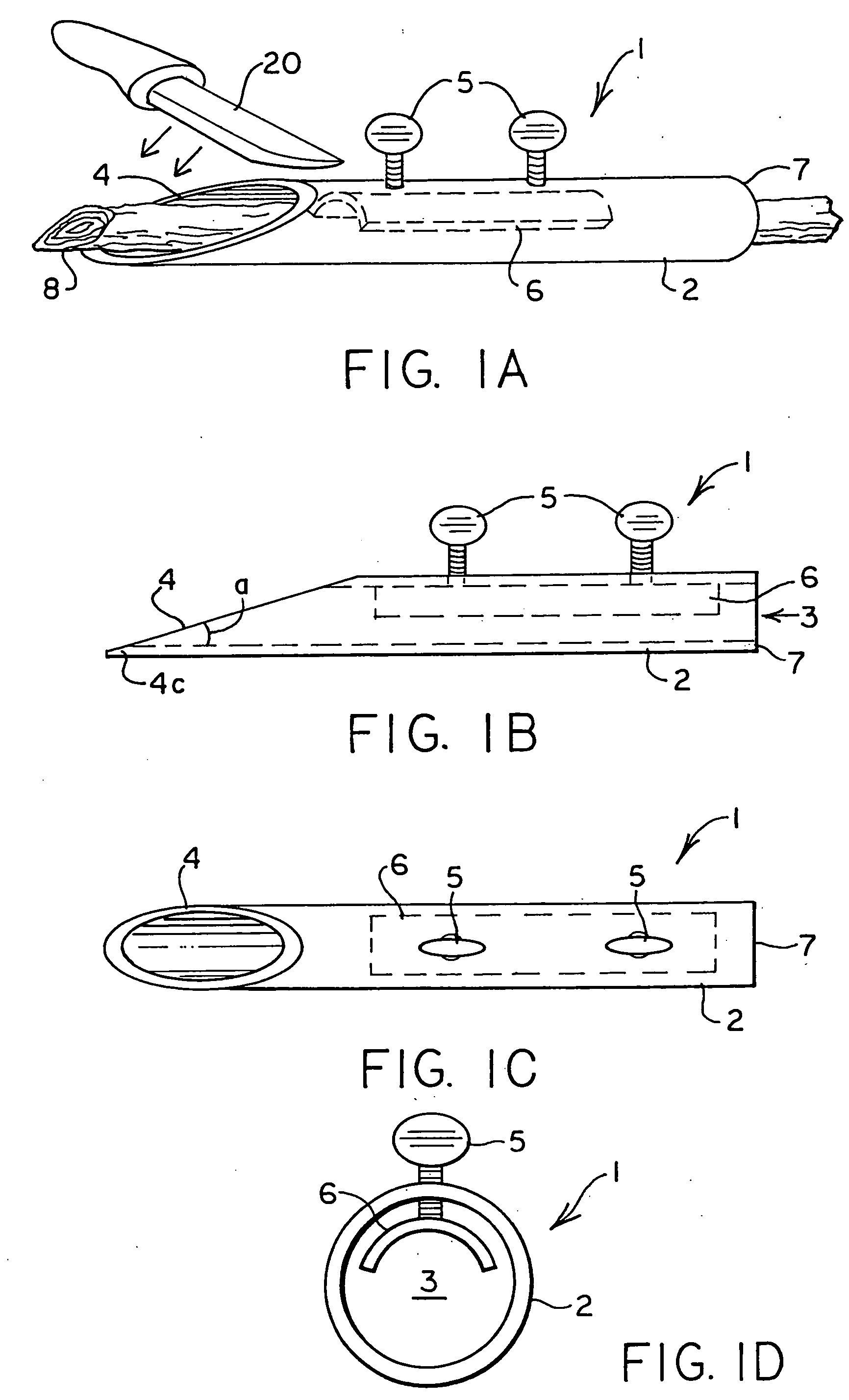
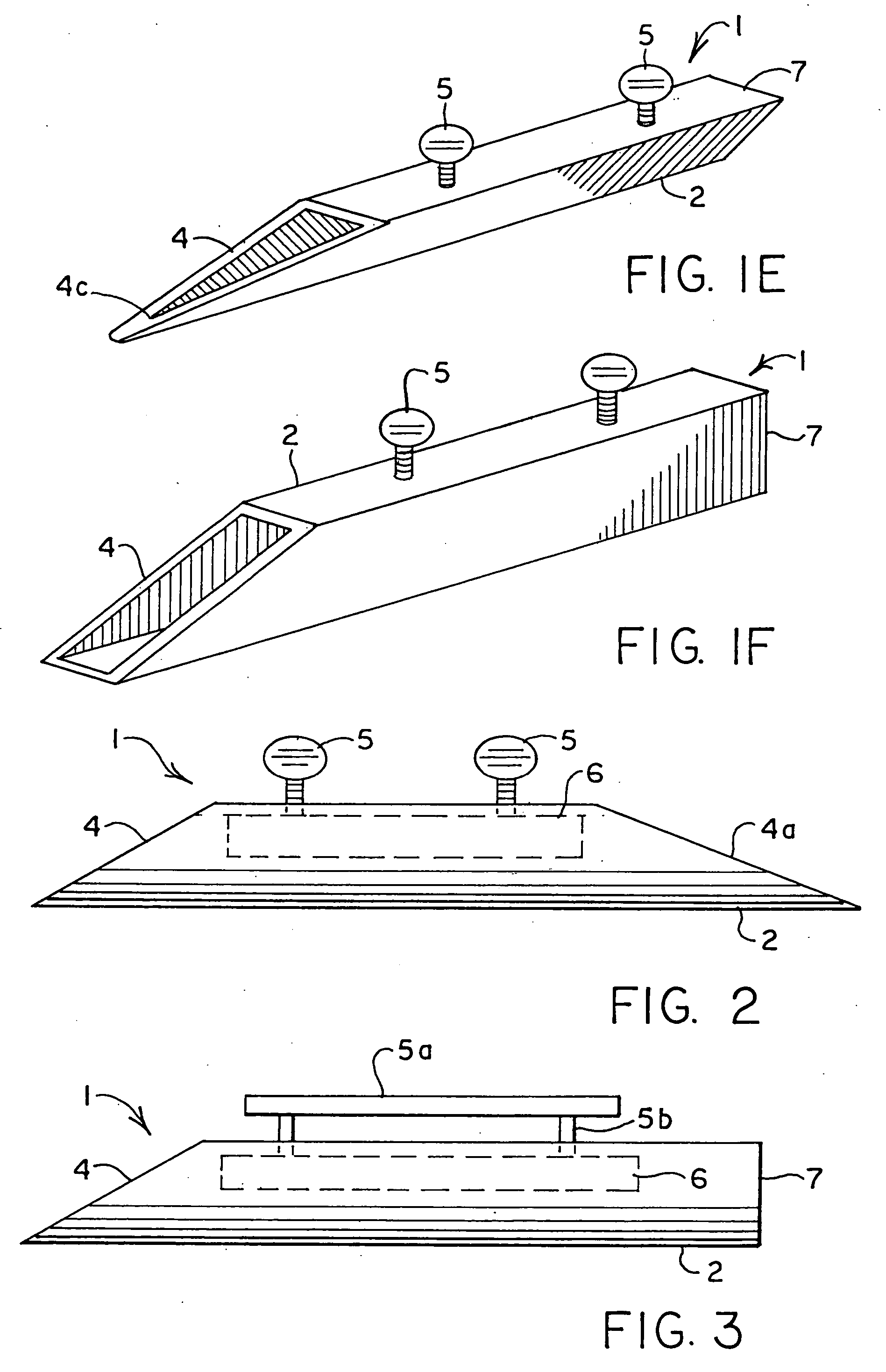
[0022] For the embodiment of this invention shown in FIGS. 1A-1D, the grafting tool 1 comprises a hollow housing (or “chamber”) 2 that has a bore 3 there through. The grafting tool 1 has been constructed such that from a side perspective there is an angled end 4. The angled end has an angle so that when a stem is placed in the housing such that it extends beyond the end, a knife can be used to cut the stem by sliding the knife down the face of the end to thereby make a cut at the same angle as that of the end of the tool. In general, the angle of the end is such that a stem having a diameter of approximately one-quarter inch will be cut to expose an inch to an inch and one-half (or even up to two inches) of the a diagonal cut on the stem. The angle “a” in FIG. 1B is measured based on the angle formed at the intersection of the bore to the face of the end at the point 4c of the grafting tool 1. The angle of the end can thus vary, with “a” typically being in the range from about 5 to ...


PUM


Abstract

A method of cutting a stem to be whip grafted, comprising: securing the stem in a bore of a hand-held grafting tool that includes an angled end, with a portion of the stem extending out from the angled end; drawing a knife across a face of the angled end to thereby cut the stem; and removing the cut stem from the grafting tool. In one respect the hand-held grafting tool comprises a housing having a bore and at least one angled end, a holding member, and moveable connectors attached to the holding member, wherein the moveable connectors protrude through and bisect the housing.

Description

BACKGROUND OF INVENTION [0001] This invention pertains to a device useful for whip grafting in the field of horticulture. [0002] A whip-graft is one of the most commonly used of the grafting methods. The whip-graft is used in the propagation of both fruit and ornamental trees. When making the cut on the scion and understock, it is of primary importance to use a scion and understock of the same diameter. Frequently, the length of the scion which had been cut from a shoot from, for example, the preceding year is most workable when cut to a four to six inch length and one-fourth inch in diameter. In the past it has been difficult to mate the two because of uneven cuts owing to too severe of an angle or not enough of an angle. [0003] The present inventor has determined that a need exists for a tool that ensures that the cambium layers are properly mated at the correct angle. In either of these circumstances, poor contact between the two cambium layers of the stock to be mated results in...

Claims


Application Information

Patent Timeline
Patent Type & Authority Applications(United States)
IPC IPC(8): A01G1/06B26B29/06
CPCB26B29/06A01G1/06A01G2/35
Inventor SOWINSKI, THOMAS
Owner SOWINSKI THOMAS
Why Eureka
Try Eureka