Technique for detecting and predicting air filter condition

a technology of air filter and condition prediction, applied in auxillary pretreatment, instruments, separation processes, etc., can solve the problems of premature component failure, reduced cooling and heating capacity, and increased power consumption

Inactive Publication Date: 2005-11-10
CARRIER CORP
View PDF20 Cites 157 Cited by
  • Summary
  • Abstract
  • Description
  • Claims
  • Application Information

AI Technical Summary

Benefits of technology

This patent describes a system that can detect and predict the condition of an air filter without needing extra sensors. It works well for variable blower systems and can even predict when the air filter will need to be replaced.

Problems solved by technology

The technical problem addressed in this patent is the need for a method to detect the condition of air filters in heating, ventilating, and air conditioning systems without the need for additional sensors that increase cost and complexity. Current filter detection systems require additional sensors and controls that only detect the clogging of filters, rather than predicting when they will need replacement. The invention aims to develop a system that can detect and predict air filter condition using information already available within the system, and that is effective for variable blower systems.

Method used


Image

  • Technique for detecting and predicting air filter condition
  • Technique for detecting and predicting air filter condition
  • Technique for detecting and predicting air filter condition

Examples


Embodiment Construction

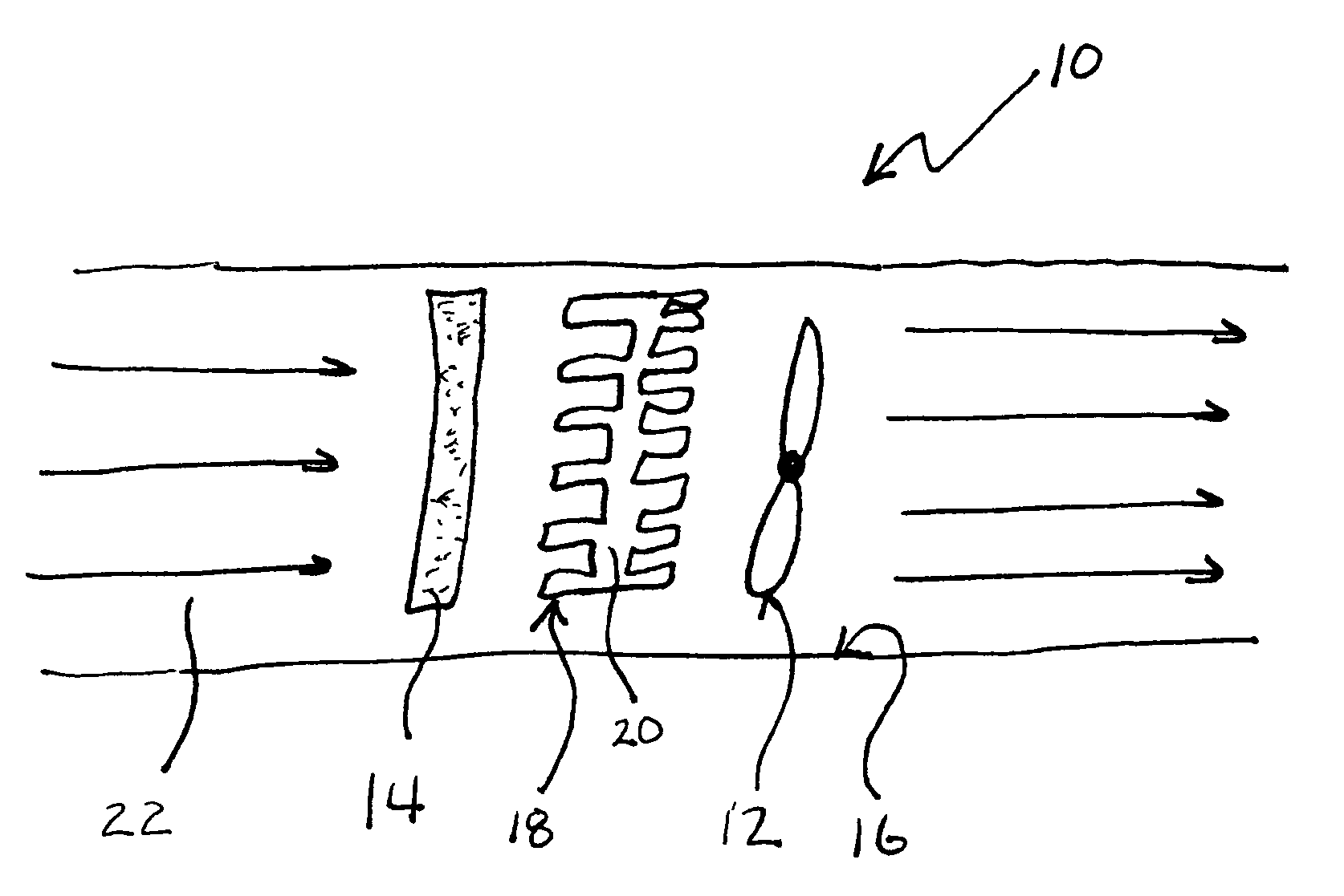
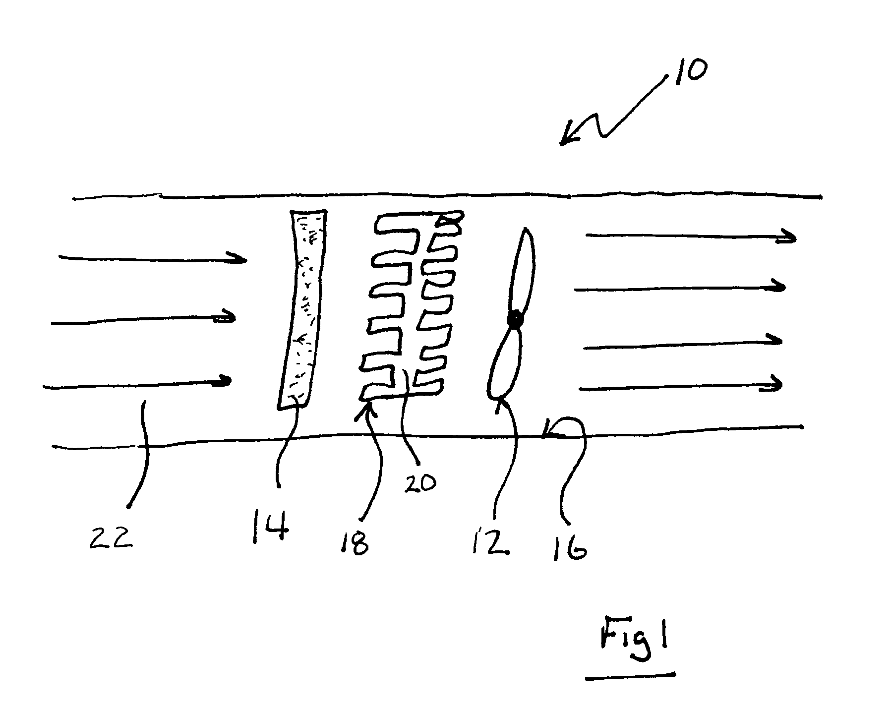
[0020] A method of detecting and predicting air filter clogging for an air handling system 10 for a Heating, Venting and Air Conditioning (HVAC) system is disclosed. Referring to FIG. 1, the system 10 is schematically shown and includes a fan 12 providing airflow 22. An air filter 14, duct 16 and heat exchanger 20 having fins 18 resist the airflow 22. The condition of the filter 14 is detected by measuring system resistance to air flow 22 and determining that the air filter 14 is clogged once the system resistance reaches a predetermined value. One of ordinary skill in the art will recognize that the placement of fan 12 after heat exchanger 20 and filter 14 with respect to air flow 22 may be changed without affecting the filtering performed by filter 14 or the slow accumulation of unfiltered debris on heat exchanger 20.

[0021] Resistance to airflow 22 is caused by plugging of the air filter 14 and occurs relatively quickly compared to resistance caused by clogging of the ducts 16 or...


PUM

PropertyMeasurementUnit
Temperatureaaaaaaaaaa
Timeaaaaaaaaaa
Pressureaaaaaaaaaa

Abstract

A method and system for detecting and predicting air filter condition for an air handling system operates by determining a system resistance to air flow. The system resistance is utilized to determine a detection statistic indicative of current filter condition and to predict remaining life of the air filter. The system resistance is determined using models that approximate the expected operation of the air handling system. The approximation is then compared to actual values to obtain a difference. Once the difference between the approximated value exceeds a threshold value, an alarm is initiated that is indicative of system resistance. The remaining air filter life is then determined by using historically gathered data, or by using a known degradation rate of the air filter. Once the remaining life of the air filter is estimated, replacement can be scheduled that would coincide with other maintenance.

Description


Claims


Application Information

Patent Timeline
Owner CARRIER CORP
Why Eureka
Try Eureka