Motor drive apparatus equipped with life prediction function for motor brake

a technology of motor brakes and motor drives, which is applied in the direction of stopper details, dynamo-electric machine testing, vehicle components, etc., can solve the problems of inefficiency in maintenance work, method may not be desirable, and inability to predict the time when the life of the friction brake apparatus comes to an end, so as to achieve the effect of reducing power consumption

Active Publication Date: 2017-04-20
FANUC LTD
View PDF0 Cites 5 Cited by
  • Summary
  • Abstract
  • Description
  • Claims
  • Application Information

AI Technical Summary

Benefits of technology

[0014]In view of the above problems, it is an object of the present invention to provide a small-sized and low-cost motor drive apparatus capable of predicting the life of a friction brake apparatus with lower power consumption.

Problems solved by technology

However, this method may not be desirable because power is consumed wastefully as the brake is released by application of a wastefully high brake coil voltage in a state in which there is a small amount of wear in the friction plate 111, which has only been used for a short period of time, of the friction brake apparatus 100.
However, according to the inventions described in Japanese Patent Publication No. 3192817 and Japanese Laid-open Patent Publication No. 2015-466, it is possible to detect life arrival (in other words, occurrence of a failure) due to wear of a friction plate in a friction brake apparatus, but it is not possible to predict a timing when the life of the friction brake apparatus comes to an end.
For example, provided it is possible to predict the timing when the life of the friction brake apparatus comes to the end, it is efficient in that it is possible to perform maintenance work such as repair, replacement or the like during a time slot for which the friction brake apparatus is not used such as close of business time, but according to the invention described in Japanese Patent Publication No. 3192817, it is inefficient in that the maintenance work is performed after occurrence of a failure in the friction brake apparatus is detected.
Further, according to the invention described in Japanese Patent Publication No. 3192817, since the brake coil voltage applied to the brake coil remains constant regardless of the deterioration state of the friction plate, particularly, failure detection is performed by application of an uneconomically high brake coil voltage even in a state in which the amount of wear of the friction plate is small due to the duration of use of the friction brake apparatus being short, and thus, undesirably, power is consumed wastefully.
Further, according the invention described in Japanese Laid-open Patent Publication No. 2002-303344, in order to predict the life of the vehicle's brake element, it is required that a circuit for measuring a running distance of the vehicle corresponding to a thickness of a friction plate be separately provided in the brake apparatus, and hence there is a problem in that the number of parts is increased, which leads to an increase in size as well as an increase in cost of the apparatus.

Method used


Image

  • Motor drive apparatus equipped with life prediction function for motor brake
  • Motor drive apparatus equipped with life prediction function for motor brake
  • Motor drive apparatus equipped with life prediction function for motor brake

Examples


Embodiment Construction

[0024]A motor drive apparatus equipped with a life prediction function for a motor brake will be described below with reference to the drawings. It should be understood that the present invention is not limited to the drawings or embodiments described below.

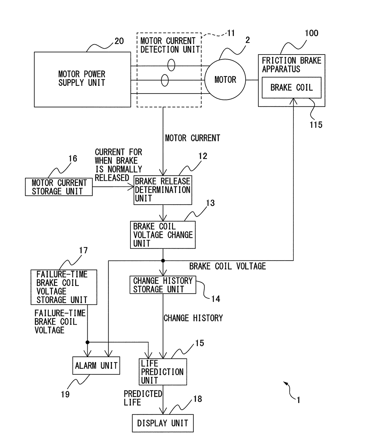
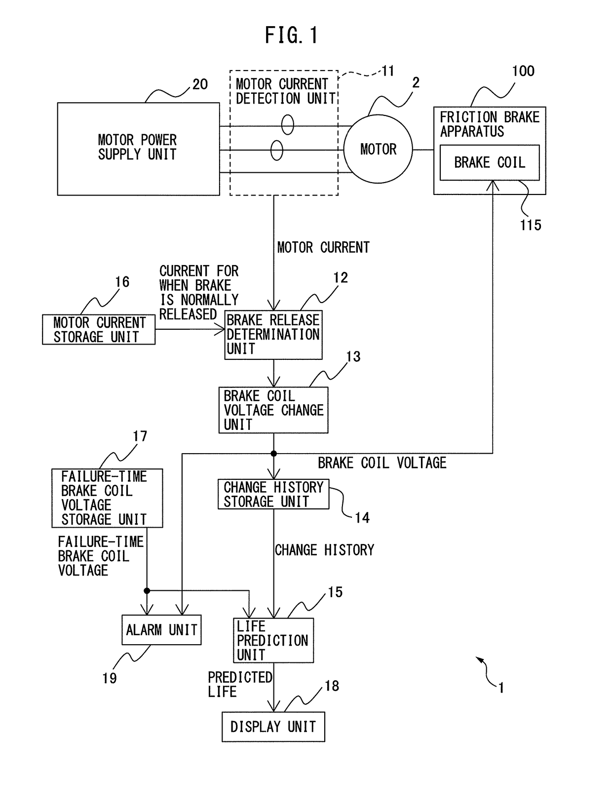
[0025]FIG. 1 is a principle block diagram of a motor drive apparatus according to an embodiment. Description will herein be made of a case in which a motor 2 is controlled by a motor drive apparatus 1. Incidentally, although, in the example illustrated in FIG. 1, the motor 2 is an AC motor, the type of the motor 2 does not limit the present invention, and the motor may be a DC motor. Further, when the motor 2 is an AC motor, it may be an induction motor or a synchronous motor. Further, the method for driving the motor 2 does not limit the present invention, but may be any known driving method.

[0026]The motor drive apparatus 1 includes a motor power supply unit 20 and a friction brake apparatus 100.

[0027]The motor power supply uni...


PUM


Abstract

A motor drive apparatus includes: a motor current detection unit; a brake release determination unit that determines that the brake is not released when the motor current detected when the motor is operated under a predetermined load by application of a voltage to a brake coil is larger than a current for when the brake is normally released; a brake coil voltage change unit that changes a voltage applied to the brake coil when it is determined that the brake is not released to a larger value; a change history storage unit that stores the voltage after being changed and change date and time; and a life prediction unit that calculates a predicted life of the brake apparatus based on the voltage after being changed and the change date and time and the previously stored failure-time brake coil voltage.

Description

BACKGROUND OF THE INVENTION[0001]1. Field of the Invention[0002]The present invention relates to a motor drive apparatus equipped with a friction brake apparatus for braking a motor with a friction plate.[0003]2. Description of the Related Art[0004]In a motor drive apparatus, use is conventionally made of a friction brake apparatus for braking a motor with a friction plate held between an armature and an end plate. FIGS. 3A and 3B are sectional views illustrating a structure of a general friction brake apparatus.[0005]In a friction brake apparatus 100, a friction plate 111 is interposed between an armature 112 and an end plate 113. A hub 122 is spline-coupled to the friction plate 111 and is made integral with a shaft 121 of a motor by shrink fitting such that the friction plate 111 is also rotated in linkage with rotation of the shaft 121 of the motor. The end plate 113 and a spacer 117 are coupled together by a bolt 118, and the armature 112 is coupled to the spacer 117 so as to b...

Claims


Application Information

Patent Timeline
Patent Type & Authority Applications(United States)
IPC IPC(8): F16D66/02
CPCF16D66/022G01R31/34H02P3/04B60T17/221
Inventor SAITO, SOUSHIKAGAWA, TSUTOMUINABA, KIICHI
Owner FANUC LTD
Why Eureka
Try Eureka