Microfluidic devices with separable actuation and fluid-bearing modules

Inactive Publication Date: 2005-11-10
THE AEROSPACE CORPORATION
View PDF92 Cites 23 Cited by
  • Summary
  • Abstract
  • Description
  • Claims
  • Application Information

AI Technical Summary

Benefits of technology

[0038] The five-layer Peltier sandwich structure controls the temperature of the thermal control volume element 408 in a substantially uniform manner as follows. An electric current is caused to flow through the sandwich in a direction from the n-type semiconductor through the silver layer to the p-type semiconductor. This will cause heat to be absorbed due to the Peltier effect at both faces of the silver layer. Since the thermal conductivity of silver is at least two orders of magnitude higher than the thermal conductivities of the materials surrounding it (including BiTe, the fluid, and the substrate of the fluid-bearing module 402), the temperature of the silver will be approximately uniform. The Peltier effect will also cause heat to be released at each of the junctions between the BiTe and the copper layers. This heat will be dissipated by thermal conduction through the copper conduction layer into the heat-sink layer. The temperature of the silver layer will thus be maintained at a uniform value lower than the temperature of the heat-sink layer. The minimum temperature that can be maintained in the silver layer is limited by thermal conduction in all adjacent layers, and by ohmic heating in the BiTe layers, but it is sufficiently low to freeze water-based fluids when the heat sink is maintained at normal room temperatures. Running the electric current in the reverse direction, from the p-type semiconductor through the silver layer to the n-type semiconductor, will produce the opposite effect. Heat will be released at the two faces of the silver layer and absorbed at the copper-BiTe interfaces. The silver layer can thus be maintained at a uniform temperature higher than the temperature of the heat sink. The maximum tempera

Problems solved by technology

For example, if the same instrument is used for analyzing a series of blood samples from separate patients, it is considered completely unacceptable for any residue from one sample to remain in the instrument where it might contaminate a later sample.
Although all these functions have been d

Method used


Image

  • Microfluidic devices with separable actuation and fluid-bearing modules
  • Microfluidic devices with separable actuation and fluid-bearing modules
  • Microfluidic devices with separable actuation and fluid-bearing modules

Examples


Example

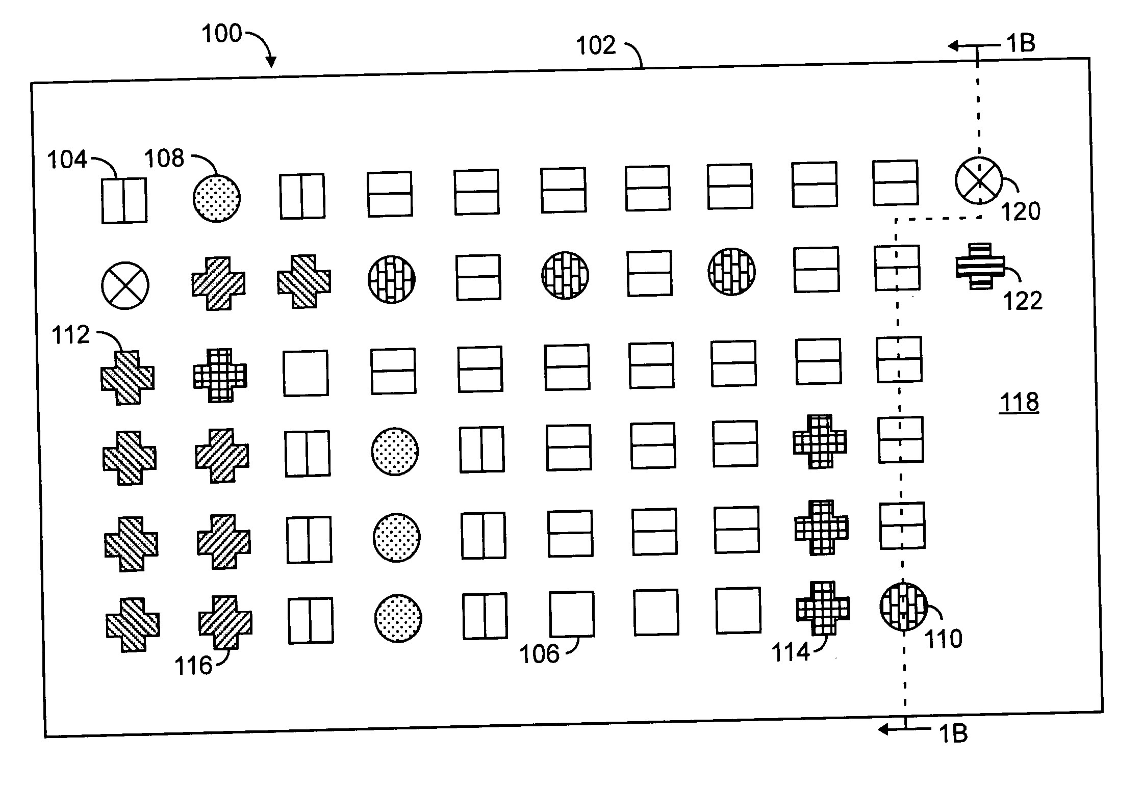
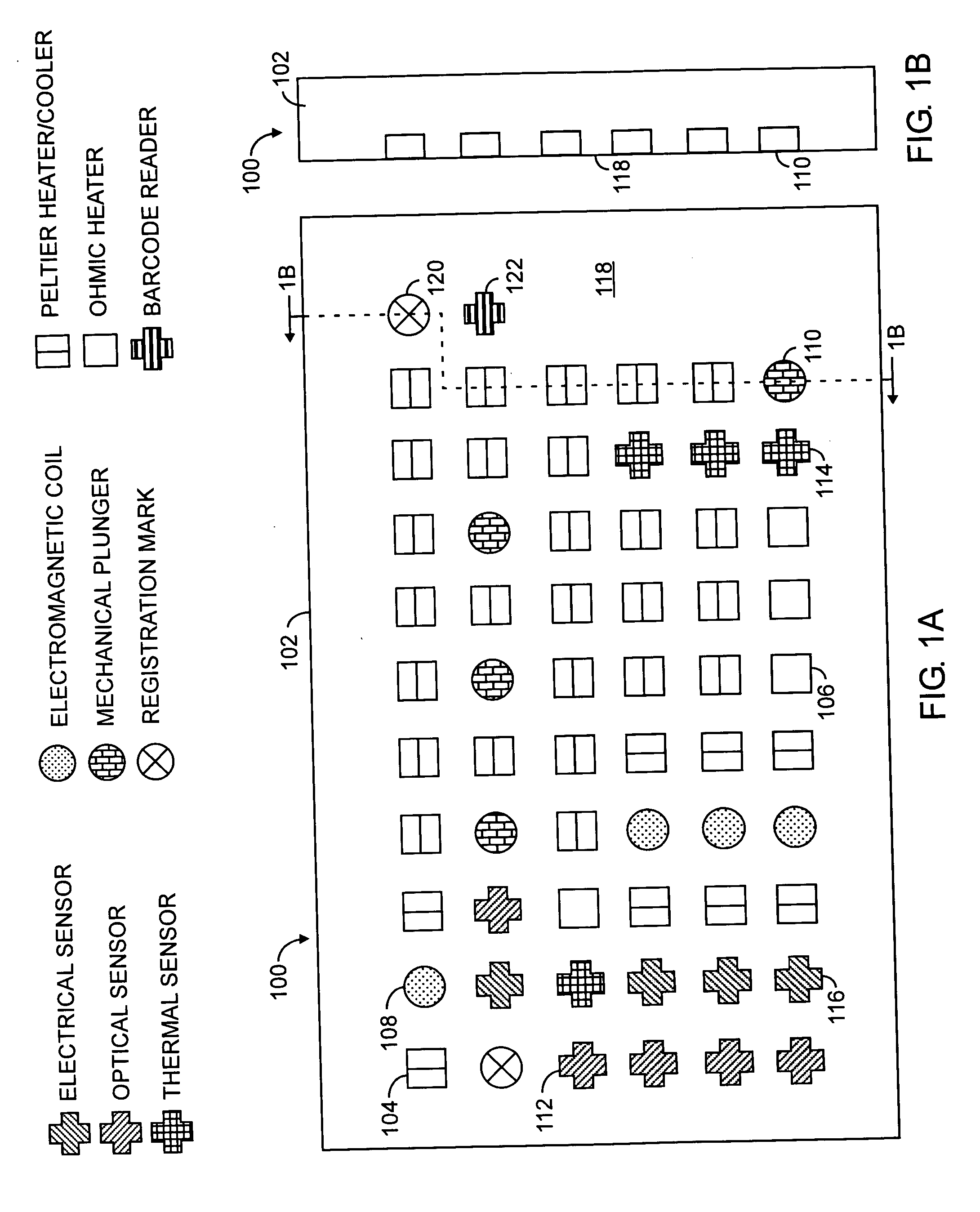
[0026] For purposes of this description, a “microfluidic” device or valve has one or more channels with at least one dimension less than 1 mm.

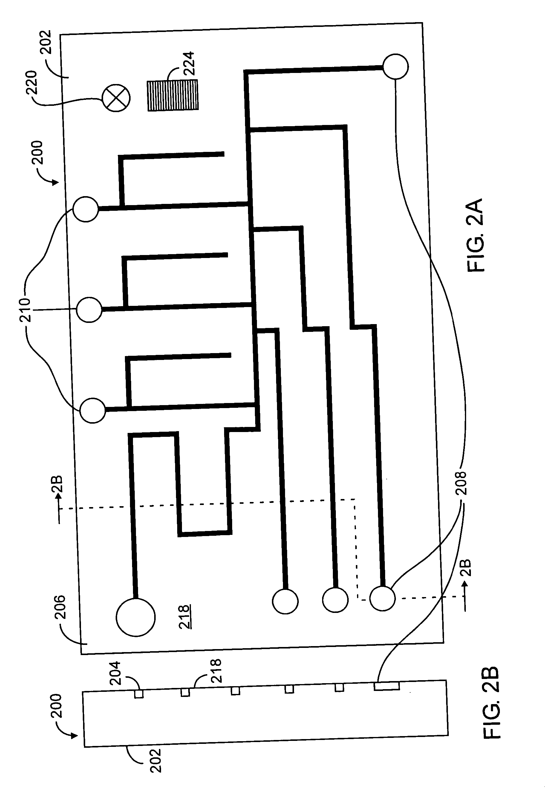
[0027] According to various embodiments of the present invention, a microfluidic device is provided by two operatively interfaced modules, namely, a fluid-bearing module and an actuator module. The fluid-bearing module incorporates fluid transport / containment elements and other elements that may come into contact with fluids. The actuator module incorporates actuation mechanisms for fluid transport and control. The two modules are brought together into contact for use. The modules are detachably secured to each other thereby allowing the fluid-bearing module, when it is no longer needed, to be separated from the actuator module and disposed of. The actuator module, on the other hand, is reusable with another fluid-bearing module, eliminating in many instances the possibility of cross-contamination between fluids in the two fluid-bearing modul...


PUM


Abstract

A fluid transport/containment apparatus includes a fluid-bearing module and an actuation module. The fluid-bearing module includes a substrate and fluid transport/containment elements distributed therein, with one or more of the fluid transport/containment elements having microfluidic dimensions. The actuation module is detachably secured to the fluid-bearing module such that the actuation elements are operatively interfaced with the fluid transport/containment elements.

Description

CROSS-REFERENCE TO RELATED APPLICATIONS [0001] This application is a continuation-in-part of U.S. patent application Ser. No. 10 / 843,515 entitled “Phase-Change Valve Apparatuses” filed on May 10, 2004, which is incorporated herein by reference in its entirety.TECHNICAL FIELD [0002] The invention relates generally to devices and valves for controlling fluid flow and, in particular, to microfluidic devices and valves. BACKGROUND ART [0003] Developments in miniaturization and large-scale integration in fluidics have led to the concept of creating an entire chemistry or biology laboratory on a fluidic analog of the electronic microchip. Such integrated microfluidic devices (known as Micro Total Analysis Systems, or μTAS) are seen as key to automating and reducing costs in many biological analysis applications, including genetic analyses and medical diagnostics. When conducting such biological analyses, however, it is often important to avoid the possibility of cross-contamination betwee...

Claims


Application Information

Patent Timeline
IPC IPC(8): F15C1/04F15C5/00F16K99/00G05D7/00
CPCB01L3/502738B01L2300/1822B01L2400/0677F15C5/00F16K2099/0084F16K99/0003F16K99/0021F16K99/0044F16K99/0001Y10T137/2196Y10T137/5283Y10T137/2191Y10T137/2224Y10T137/2213
Inventor WELLE, RICHARD P.
Owner THE AEROSPACE CORPORATION
Why Eureka
Try Eureka