Low-profile thermosyphon-based cooling system for computers and other electronic devices

a cooling system and thermosyphon technology, applied in the direction of lighting and heating apparatus, instruments, and semiconductor/solid-state device details, can solve the problems of insufficient space for cooling fins to extend above the condenser, the cooling properties are not significantly changed, and the available height is severely limited. achieve the effect of preventing chip damage or scratching, large surface area for heat distribution, and not significantly changing cooling properties

Active Publication Date: 2011-06-14
BELITS COMP SYST
View PDF20 Cites 41 Cited by
  • Summary
  • Abstract
  • Description
  • Claims
  • Application Information

AI Technical Summary

Benefits of technology

[0027]The pipes connecting the evaporator and condenser are attached to one of the long sides of the condenser, either near the middle or near one of the ends of the condenser. The coolant pipes are connected to the sides of the condenser at or near the bottom of the condenser, and the vapor pipes are connected to the sides of the condenser at or near the top of the condenser. When used for cooling computer components, the routing of the pipes between the evaporator and condenser is determined by the space available inside the computer case. The coolant pipes are routed around capacitors, coils, small chips' heatsinks, power and fan connectors and RAM sockets. The vapor pipes can go above most of the devices except the RAM, power connectors and other tall parts. The shape of the pipes should not affect the efficiency of the cooling device as long as the coolant pipes allow the liquid coolant to flow unimpeded, and the vapor pipes do not drop below the level of the liquid. The device is easier to install and less affected by tipping when the length of the pipes is shorter.
[0040]Usually heatsinks and other cooling devices are attached to CPUs and other heat sources using brackets and clips. A cooling device of the present invention should use a strong bracket to attach the evaporator to the heat source. The bracket should not induce bending forces that are higher than ones produced by traditional heatsinks. Also the bracket should avoid application of uneven pressure, tilting or application of the whole force to only one edge of the chip while the device is being installed. To accomplish this goal, a special bracket and locking spring is used. A reverse U-shaped bracket is attached to the computer case, board, standoffs or a socket just like any standard heatsink bracket. However the bracket should be taller than usual and cover the whole evaporator, leaving space between the top of the evaporator and a bracket to fit a vaguely S-shaped spring. The S-shaped spring should contact the evaporator or the evaporator's cover plate in the center directly above the center of the chip. When installed, the spring is rotated and bends until it latches with the bracket, keeping the device secure. To remove the evaporator the ends of the spring are pressed, releasing the latched ends, and the S-shaped spring is rotated back until it releases the evaporator. This mechanism ensures that force is always applied to the center of the evaporator and is directed downwards, toward the center of the chip. This prevents the damage to the chip or scratching of the evaporator, and allows the user to achieve good thermal contact even if installation is performed in a cramped environment that is common in data centers. The same bracket and S-spring mechanism can be used for other applications, such as attaching regular heatsinks that do not require an open top.

Problems solved by technology

This placement is not possible in spaces where the available height is severely limited.
In spaces where the available height is severely limited, cooling fins do not have enough space to extend above the condenser.

Method used


Image

  • Low-profile thermosyphon-based cooling system for computers and other electronic devices
  • Low-profile thermosyphon-based cooling system for computers and other electronic devices
  • Low-profile thermosyphon-based cooling system for computers and other electronic devices

Examples


Embodiment Construction

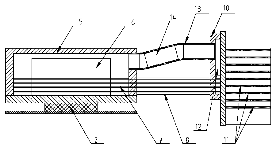
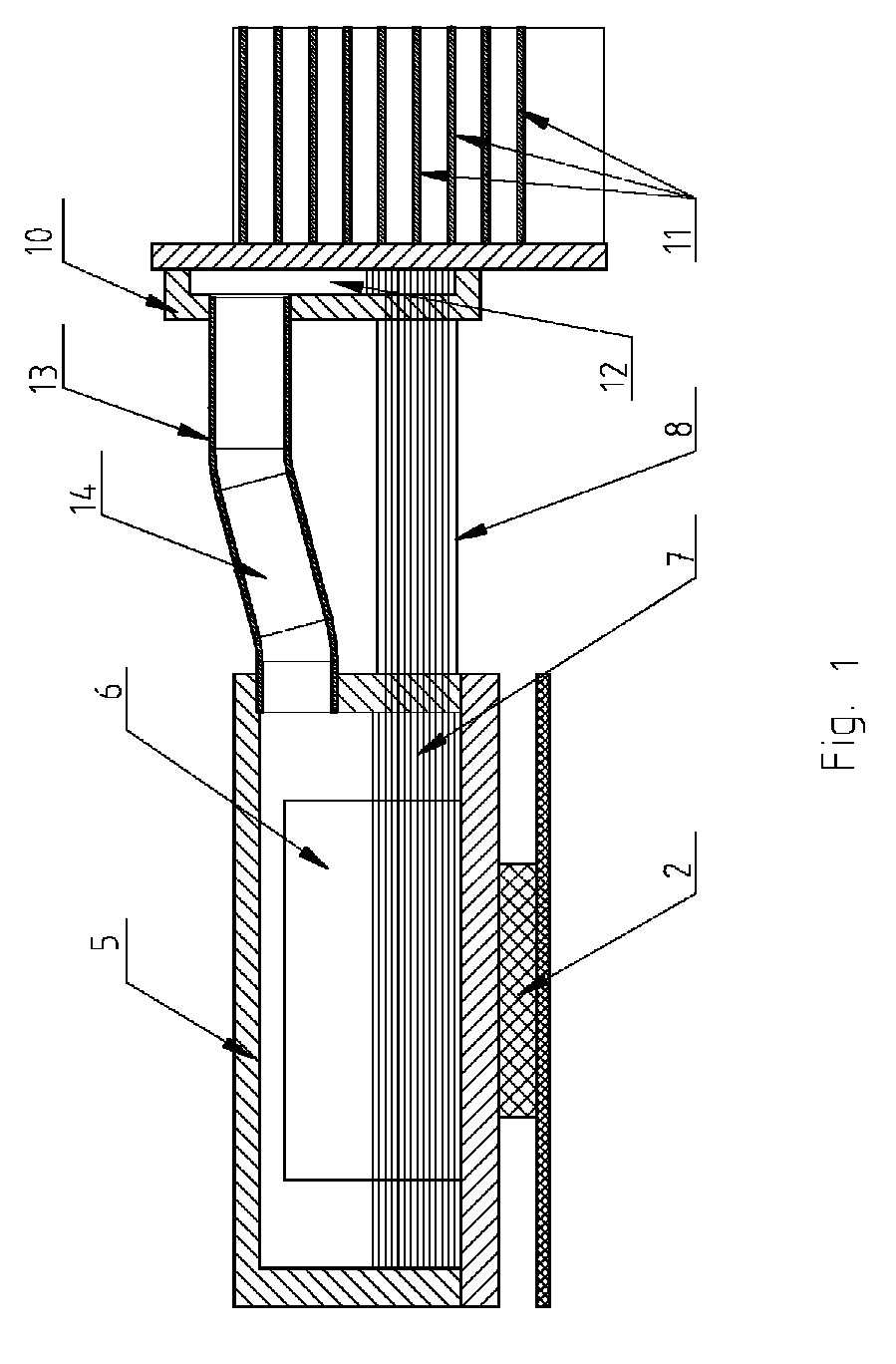
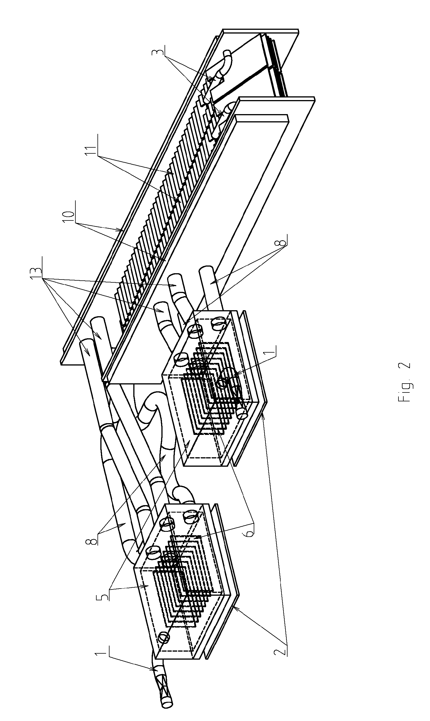
[0047]High-density servers are placed in rack-mountable cases approximately 17 inches to 19 inches wide and 1.75 inches high, or less, when laid flat. All devices, including cooling devices, within the case must fit within these dimensions. The height of the floor of the case, standoffs, circuit board, CPU socket and CPU itself leaves only about 1 inch between the surface of the CPU and the top of the case, so any evaporator or heatsink attached to top of the CPU or other heat source should preferably not exceed 1 inch in height. A thermosyphon device within a case such as this will need to work with a very small amount of hydrostatic pressure moving the liquid. The load on the CPU, and therefore the heat production, may vary over the time, and the case is not necessarily placed precisely horizontally, so the design of the thermosyphon device should be suitable for varying conditions, including changes in the amount of heat produced by the CPU, level of liquid, and vapor bubbles in ...


PUM


Abstract

This invention provides a cooling system comprising a thermosyphon for computer and electronic devices. The thermosyphon comprises an evaporator placed on top of a heat source, such as CPU. Heat from the heat source causes liquid coolant inside the evaporator to evaporate or boil. The resulting vapor enters a condenser and returns to a liquid phase. Cooling fins are attached to the condenser to facilitate heat transfer with the surrounding airflow. The cooling system and computer or electronic device fit within standard computer cases and high density server rack-mountable cases.

Description

CROSS-REFERENCE TO RELATED APPLICATIONS[0001]This application is a continuation-in-part of pending U.S. application Ser. No. 11 / 087,402, filed Mar. 23, 2005, which in turn claims the benefit under 35 U.S.C. 119(e) of U.S. Provisional Application No. 60 / 558,607, filed Mar. 31, 2004, all of which are incorporated in their entirety herein to the extent that there is no inconsistency with the present disclosure.BACKGROUND OF THE INVENTION[0002]Space in the data centers for servers and other computer systems is often limited. To conserve space, computer components are placed in close proximity. Cases which house servers and other computer systems are designed to take up as little space as possible. In particular, rack-mountable cases used with high density server racks are typically designed to be thin and flat in order to allow multiple servers or computer systems to be installed within the same server rack. As microprocessors and electronics become more powerful, it has proven difficul...

Claims


Application Information

Patent Timeline
Patent Type & Authority Patents(United States)
IPC IPC(8): F28D15/00H05K7/20F28D15/02F28F3/02G06F1/20H01L23/427
CPCF28D15/0266F28F3/02F28F3/12G06F1/20H01L23/427H05K7/20809F28D15/06G06F2200/201H01L2924/0002H01L2924/00
Inventor BELITS, ALEXBELITS, VALERIY
Owner BELITS COMP SYST
Why Eureka
Try Eureka