Thermal paste for improving thermal contacts

a thermal contact and thermal paste technology, applied in indirect heat exchangers, semiconductor/solid-state device details, lighting and heating apparatus, etc., can solve the problems of poor conformability and spreadability, low thermal conductivity, and deformation when exposed to humidity, and achieve the effect of improving the thermal conta

Inactive Publication Date: 2005-01-27
CHUNG DEBORAH D L
View PDF10 Cites 38 Cited by
  • Summary
  • Abstract
  • Description
  • Claims
  • Application Information

AI Technical Summary

Benefits of technology

[0021] Yet another aspect of the present invention is a method of improving the thermal contact between a first object and a second object proximate the first object, that involves disposing a layer of a thermally conductive paste made in accordance with the present invention between and in contact with the first object and the second object.

Problems solved by technology

As a fluid, it is highly conformable and spreadable, but it has a low thermal conductivity.
Due to the filler, it is relatively high in thermal conductivity, but it suffers from poor conformability and poor spreadability.
Unfortunately, however, it suffers from the disadvantage that it degrades when exposed to humidity.
Being hygroscopic, the boric acid absorbs further water, thereby accelerating the degradation of the boron nitride and diminishing its heat removing capabilities, which ultimately leads to failure of the device.
In fact, all thermal pastes previously reported are inferior to solder in providing high thermal contact conductance.
Due to its relatively low thermal conductivity, however, carbon black has not been reported as a filler for thermally conductive pastes.

Method used


Image

  • Thermal paste for improving thermal contacts
  • Thermal paste for improving thermal contacts
  • Thermal paste for improving thermal contacts

Examples


example 1

Preparation of Paste Formulations

[0047] The polyethylene glycol, HO(CH2CH2O)11H, (“PEG”) used as an organic vehicle was PEG 400 (EM Science, Gibbstown, N.J.). It had a molecular weight of 400 amu. It was a liquid at room temperature and optionally contained ethyl cellulose (Sigma Chemical Co., St. Louis, Mo.) at either 3 or 5 vol. %. The ethyl cellulose was a white powder that was dissolved in the vehicle. It served to improve the dispersion and suspension of the solids in the pastes.

[0048] The other organic vehicle used was di(ethylene glycol) butyl ether (Aldrich Chemical Co., Inc., Milwaukee, Wis.). It optionally contained ethyl cellulose (Sigma Chemical Co., St. Louis, Mo.) at 10, 20, 30 or 40 vol. %.

[0049] The carbon black used was a type for electrical conductivity and easy dispersion (Vulcan XC72R GP-3820; Cabot Corp., Billerica, Mass.). It consisted of porous agglomerates of carbon particles of particle size 30 nm, density 1.7-1.9 g / cm3, nitrogen specific surface area 254...

example 2

Thermal Contact Conductance Measurement

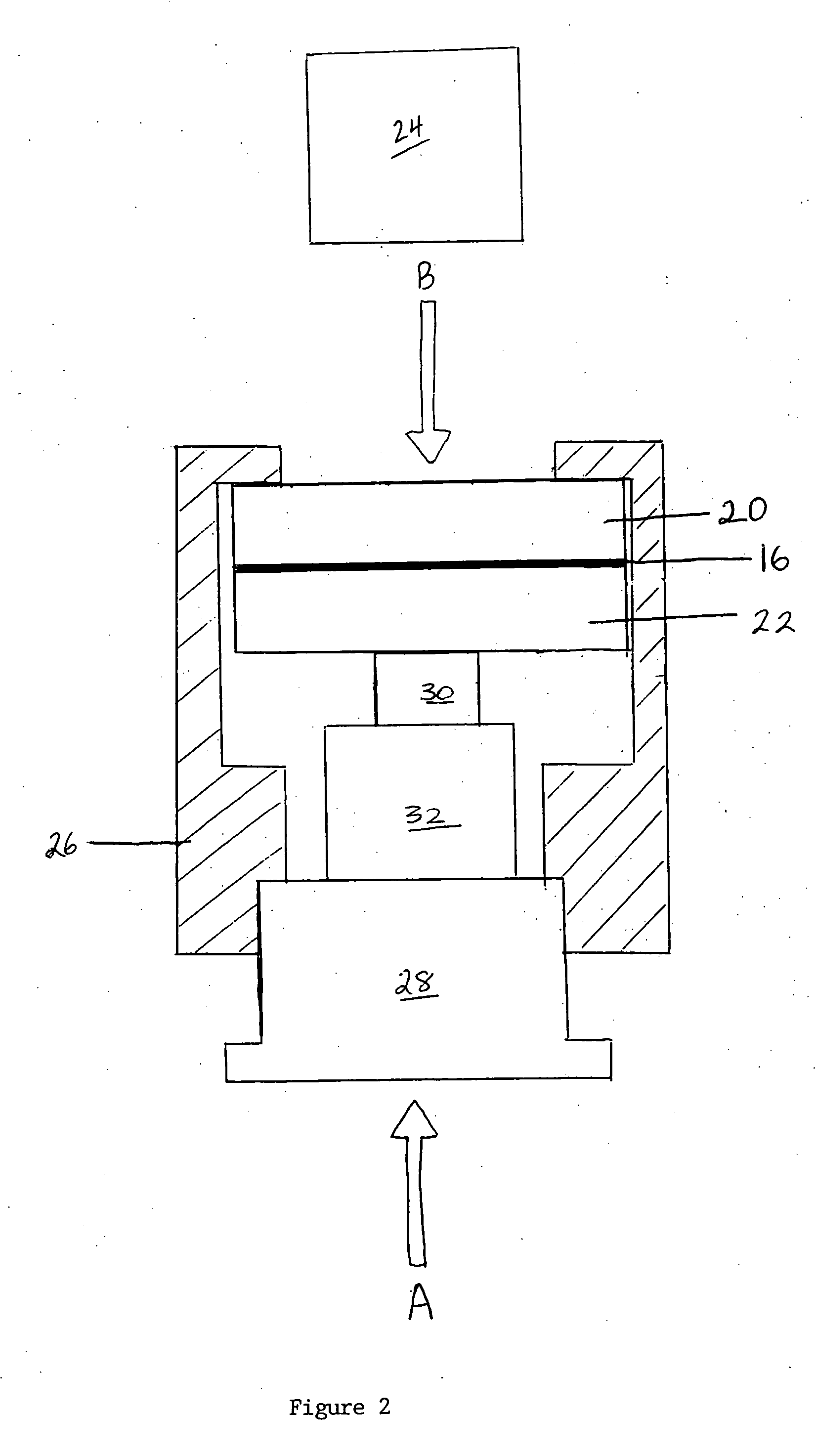
[0052] As generally depicted in FIG. 2, a layer of a thermally conductive paste 16 (or solder) was sandwiched between the flat surfaces of two copper disks 20,22 (both surfaces of each disk having been mechanically polished by using 0.05 μm alumina particles), which had diameter 12.6 mm and thickness of 1.16 mm for one disk and 1.10 mm for the other disk. The thermal contact conductance between two copper disks with and without a layer of thermally conductive paste 16 (or solder) was measured using the transient laser flash method. Xu et al., J. Electron. Pkg. 124:188-191 (2002); Xu et al., J Electron. Pkg. 122:128-131 (2000); Parker et al., J. Appl. Phys. 32:1679-1683 (1961); Inoue et al., Yosetsu Gakkai Ronbunshu / Quarterly J Jap. Welding Soc., 6:130-134 (1988), which are hereby incorporated by reference in their entirety.

[0053] The pressure on the sandwich was controlled at 0.46, 0.69 and 0.92 MPa (depicted in FIG. 2 as arrow A). This is be...

example 3

Viscosity Testing

[0059] The viscosity of the formulations was measured by using a viscometer (Brookfield Engineering Laboratories, Inc., Middleboro, Mass., Model LVT Dial-Reading Viscometer, with Model SSA-18 / 13R Small Sample Adaptor).


PUM

PropertyMeasurementUnit
vol. %aaaaaaaaaa
vol. %aaaaaaaaaa
vol. %aaaaaaaaaa

Abstract

A thermally conductive paste including porous agglomerates of carbon particles dispersed in a paste-forming vehicle is disclosed. The paste is useful as a thermally conductive interface material between a heat or cold source and an object. The paste is particularly useful as a thermally conductive interface material between a heat source and a heat sink. Apparatus and a method of removing heat from a heat source utilizing thermally conductive pastes of the present invention are also disclosed.

Description

[0001] This application claims the benefit of U.S. Provisional Patent Application Ser. No. 60 / 485,804, filed Jul. 9, 2003, which is hereby incorporated by reference in its entirety.FIELD OF THE INVENTION [0002] This invention relates to a thermally conductive paste for improving thermal contacts. BACKGROUND OF THE INVENTION [0003] With the miniaturization and increasing power of microelectronics, heat dissipation has become critical to the performance, reliability and further miniaturization of microelectronics. Heat dissipation from microelectronics is most commonly performed by thermal conduction. For this purpose, a heat sink, which is a material of high thermal conductivity, is commonly used. In order for the heat sink to be well utilized, the thermal contact between the heat sink and the heat source (e.g., a substrate with a semiconductor chip on it) should be good. Wolff et al., Heat &Mass Transfer 41 :3469-3482.(1998); Ouellette et al., Proc. Power Elec. Des. Con., Power Sour...

Claims


Application Information

Patent Timeline
Patent Type & Authority Applications(United States)
IPC IPC(8): B32B3/26B32B5/16C08K3/00F28D9/00F28F13/00H01LH01L23/34
CPCF28F13/00F28F2013/006Y10T428/26Y10T428/25H01L2224/32245Y10T428/249953Y10T428/31678H01L23/373
Inventor CHUNG, DEBORAH D.L.
Owner CHUNG DEBORAH D L
Why Eureka
Try Eureka