Support and grounding structure

a technology of supporting and grounding, applied in the direction of coupling device connection, electrical apparatus construction details, coupling device details, etc., can solve the problem of workers who are expected to be subjected to vigorous or rough handling

Inactive Publication Date: 2007-06-19
ORACLE INT CORP
View PDF10 Cites 37 Cited by
  • Summary
  • Abstract
  • Description
  • Claims
  • Application Information

AI Technical Summary

Benefits of technology

[0009]In another embodiment, a stiffening member is provided for reinforcing the circuit board against the force applied by the l...

Problems solved by technology

In blade computer systems physically robust blades may be replaceable by unskilled w...

Method used


Image

  • Support and grounding structure
  • Support and grounding structure
  • Support and grounding structure

Examples


Embodiment Construction

[0018]Embodiments and examples are described hereafter by way of example only in the following with reference to the accompanying drawings.

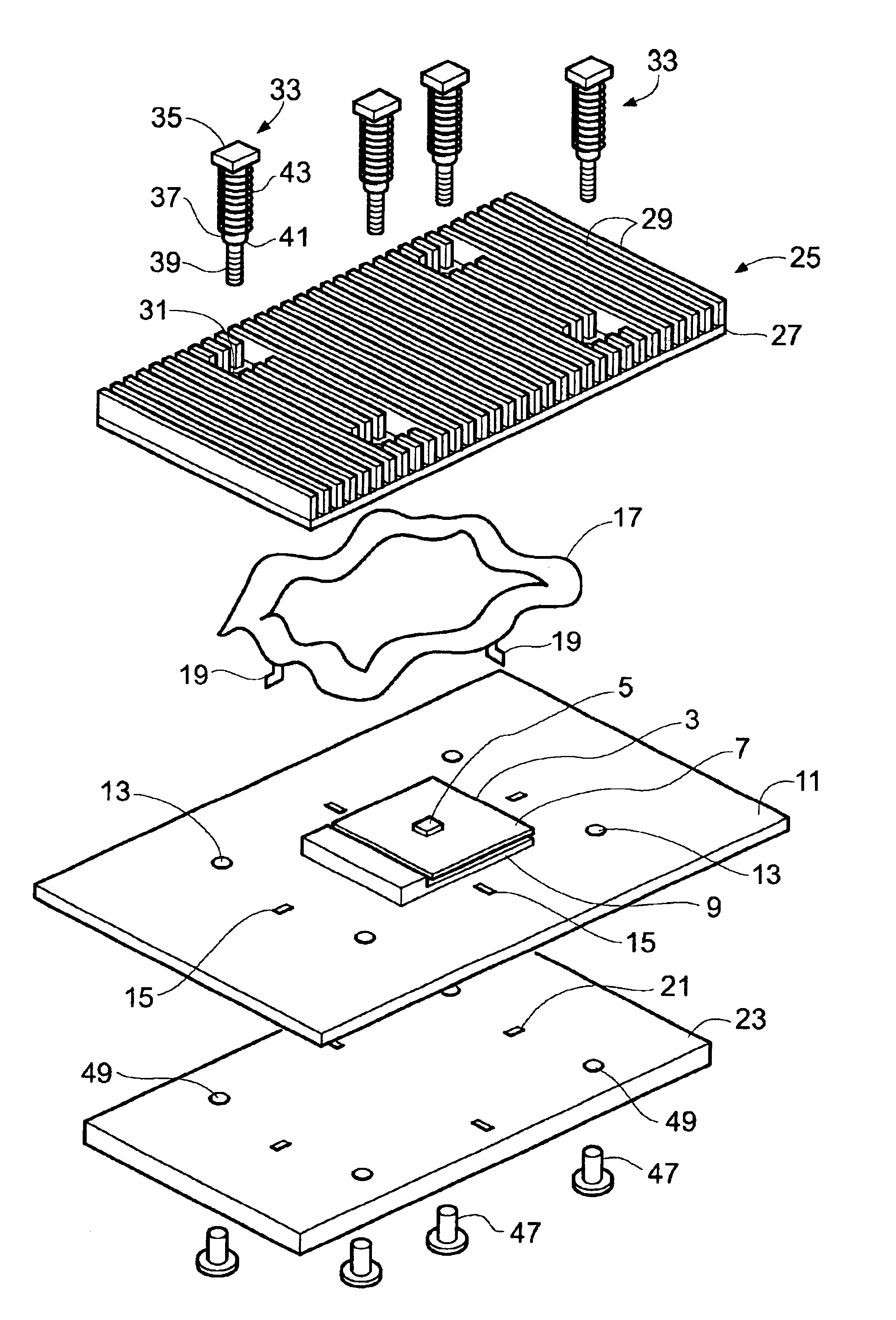
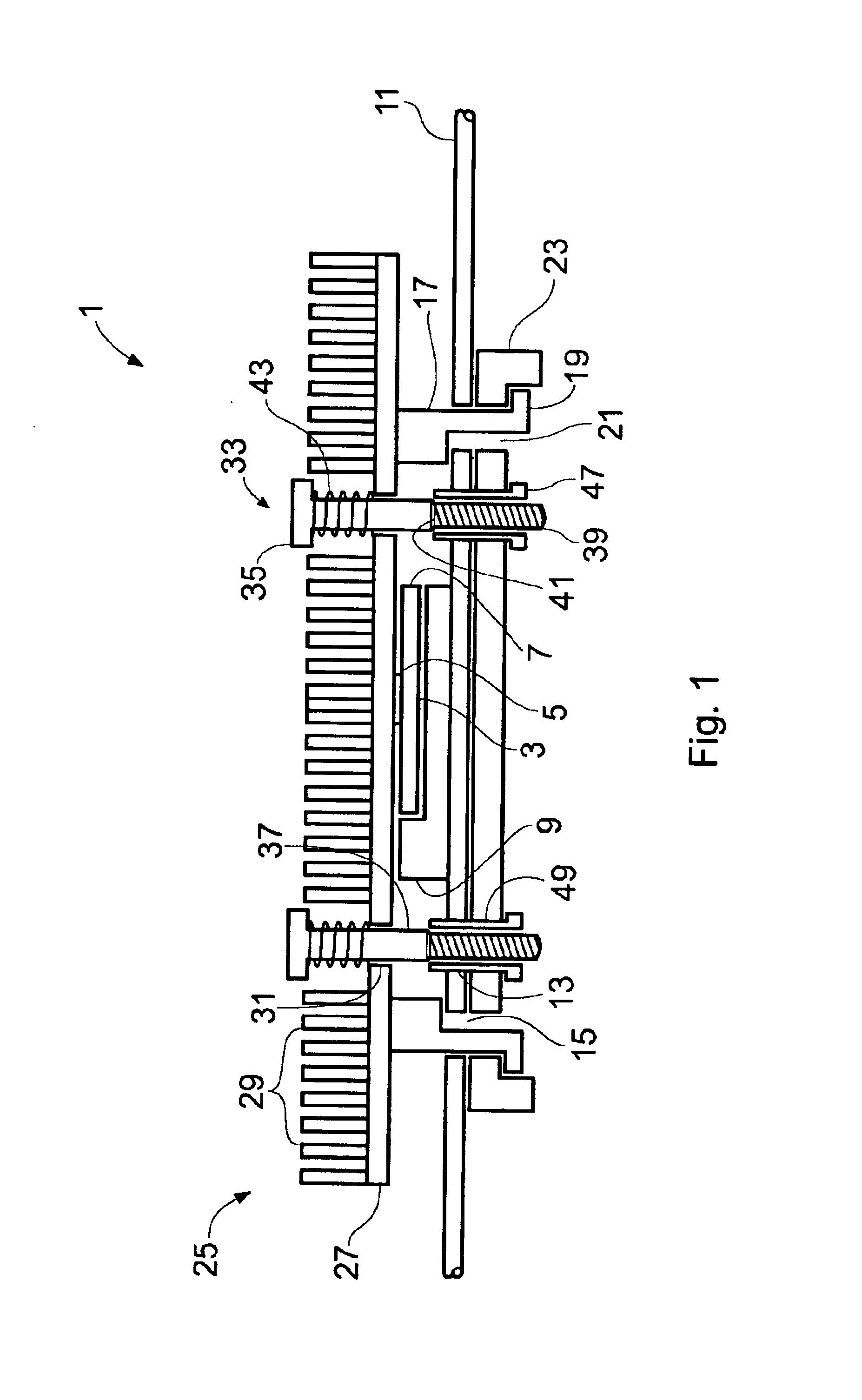
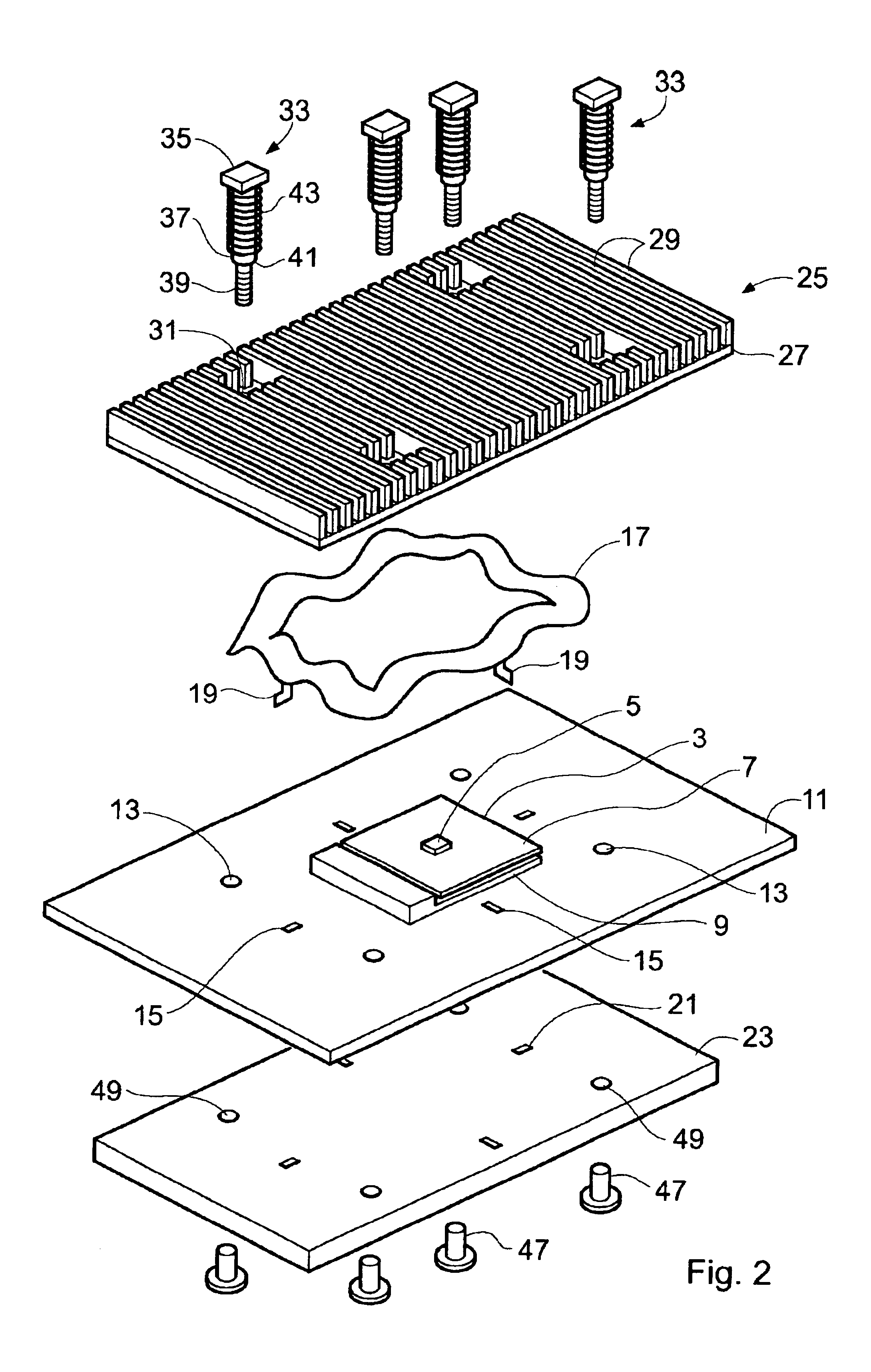
[0019]Shown in FIG. 1 is a schematic cross section view of a support and grounding structure 1 according to a first example. FIG. 2 shows the support and grounding structure of FIG. 1 from an exploded perspective viewpoint. FIG. 3 shows part of the support and grounding structure of FIG. 1 from an assembled perspective viewpoint. FIG. 4a shows a plan view of a shielding member of the support and grounding structure of FIG. 1 and FIGS. 4b and 4c show sections through the shielding member of FIG. 4a take through lines I—I and II—II respectively.

[0020]The grounding and support structure 1 is provided for a processor 3. The processor 3 of the present example has an exposed processor die 5 mounted onto a substrate 7. Examples of processors having this type of design include Celeron series processors manufactured by Intel Corporation and Athlon™ and Du...


PUM


Abstract

Various embodiments of a heat sink assembly are disclosed. In one embodiment, the heat sink assembly includes a processor mounted onto a circuit board; a heat sink located in thermal contact with the processor at the side of the processor opposite circuit board; and an electromagnetic shielding member located between the circuit board and the heat sink. The electromagnetic shielding member is releasably attached to the circuit board. Additionally, or in the alternative, the heat sink is biased toward the processor by a load spring and the electromagnetic shielding member is configured to provide a spring force between the circuit board and the heat sink, counter directional to the bias from the load spring.

Description

BACKGROUND OF THE INVENTION[0001]The present invention relates to support and grounding structures and in particular, but not exclusively to central processing unit cooler support and grounding structures within a computer system.[0002]One application for the present invention relates to computer systems where physical robustness is required. Examples of such systems include portable computing (so-called “laptop” and “notebook” computers) and in multiple processing engine server systems having replaceable processing engine cartridges or “blades”. Blade based computer systems are typically high density computer systems, which systems are typically rack mountable, with one or more processor systems occupying a shelf in the rack. In blade computer systems physically robust blades may be replaceable by unskilled workers and may be expected to be subjected to vigorous or rough handling by those workers. The trend in recent times is to make the computers with smaller form factors. This me...

Claims


Application Information

Patent Timeline
IPC IPC(8): H01R13/00H01L23/40H01L23/552
CPCH01L23/4006H01L23/552H01L2924/0002H01L2924/00
Inventor OSBORN, JAY KEVINGARNETT, PAUL JEFFREYBESTWICK, GRAHAM
Owner ORACLE INT CORP
Why Eureka
Try Eureka