Eureka AIR delivers breakthrough ideas for toughest innovation challenges, trusted by R&D personnel around the world.

Cartridge filter system

Active Publication Date: 2005-11-10
HARMSCO
View PDF36 Cites 2 Cited by
  • Summary
  • Abstract
  • Description
  • Claims
  • Application Information

AI Technical Summary

Benefits of technology

[0004] This invention relates to a filter system for removing contaminants from a contaminant laden fluid and for reducing the amount of time necessary to perform cleaning operations to remove and replace a cartridge filter. The filter system includes a tank having an opening for receiving a cartridge, a cover attached to the tank to seal the opening, and a standpipe extending from a bottom surface of the tank towards the cover. The filter system also includes a cartridge filter configured to fit in the tank. The cartridge filter may include filter media between bottom and top surfaces of the filter and an outlet tube extending from the bottom surface toward the top surface. The cartridge filter may also include at least one seal positioned in the outlet tube in closer proximity to the top surface than to the bottom surface of the filter and in contact with the standpipe. The seal forms a seal between the outlet tube of the cartridge filter and the standpipe enabling filtered fluid to be passed through the standpipe and eventually out of the filter system without contacting the contaminant laden fluid.
[0005] The seal positioned in the cartridge filter enables the cartridge filter to be attached to the standpipe and to form a seal with the standpipe proximate to the top of the tank. By sealing the standpipe to the cartridge filter above the bottom surface of the tank, the portion of the standpipe to which the seal contacts is not contacted by contaminant laden fluid when a cartridge filter is removed from the tank. Thus, this configuration advantageously eliminates the need to remove contaminated water contained in the tank once the cartridge filter has been removed and the need to clean the outside surface of the standpipe. In the rare event that the standpipe needs to be cleaned, the portion of the standpipe to which the seal in the cartridge filter contacts to form a seal is proximate to the top of the tank where it is easily accessible and does not require someone to reach into the bottom portions of the tank to clean the standpipe. These and other embodiments and advantages are described below.

Problems solved by technology

Instead, the standpipes cause the contaminant laden fluids to collect in the filter media and surrounding space in the tanks.
Many times, accessing the lower portions of the standpipe can be very difficult and time consuming.

Method used


Image

  • Cartridge filter system
  • Cartridge filter system
  • Cartridge filter system

Examples


Embodiment Construction

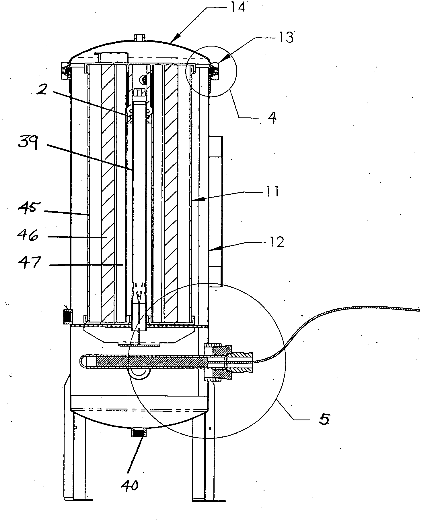
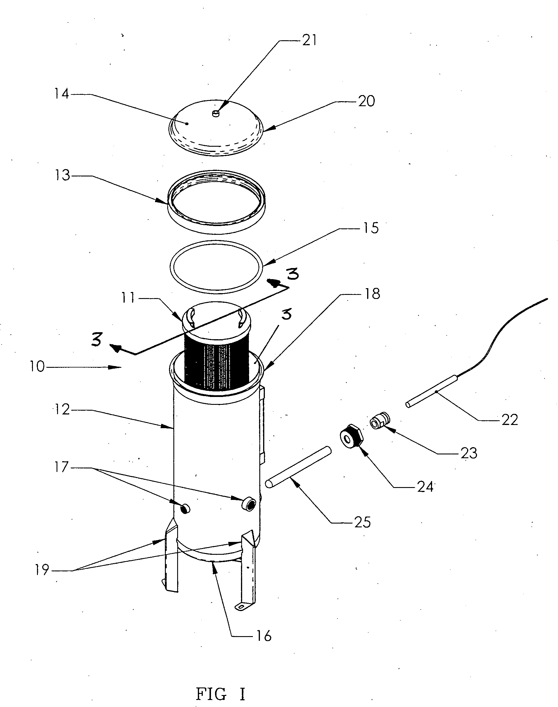
[0015] As shown in FIGS. 1-8, this invention is directed to a filter system 10 having a cartridge filter 11 with an improved sealing mechanism 2 for sealing the cartridge filter 11 to a standpipe 39 of a standpipe assembly 35. The sealing mechanism 2 may be located proximate to a cover 14 of the filter system 10 so that the portion of the standpipe 39 that contacts the seal assembly 2 is not in contact with contaminant laden fluid when the cartridge filter 11 is removed from the filter system 10. The filter system 10 enables a cartridge filter 11 to be removed and reinstalled from the filter system 10 more easily and in less time than conventional cartridge filters.

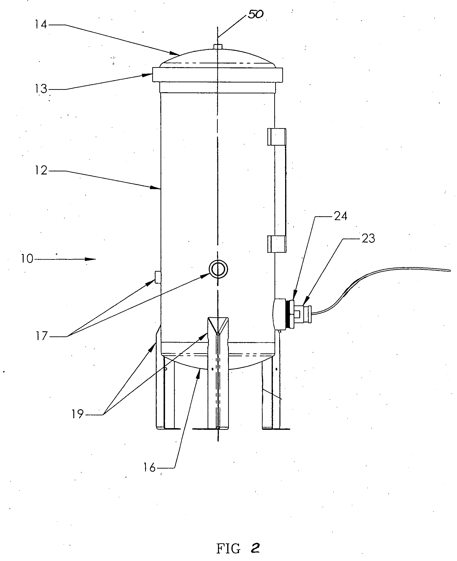
[0016] As shown in FIG. 1, the filter system 10 includes a generally hollow tank 12 having an opening 3 for receiving a cartridge filter 11. A cover 14 may seal the opening 3, and, as shown in FIG. 2, may be releasably attached to the tank 12 using any releasable mechanism, such as clamp band 13. The cover 14 may include...


PUM

PropertyMeasurementUnit
Areaaaaaaaaaaa

Abstract

A fluid filter system including a cartridge filter housed in a tank having a standpipe extending from a bottom surface of the tank. The cartridge filter is positioned in the tank with the standpipe extending into an outlet tube in the filter. Fluids flow into the tank, through the filter, and out through the standpipe. The cartridge filter may include a seal in an upper portion of the filter for sealing the cartridge filter to the standpipe in a position that is above the contaminant laden fluids and debris that collect at the bottom of a tank during removal of a cartridge filter.

Description

FIELD OF THE INVENTION [0001] This invention is directed generally to fluid filters, and more particularly to fluid filters having replaceable filters. BACKGROUND [0002] There exists numerous conventional fluid filters for removing contaminants, such as shown in U.S. Pat. Nos. 3,720,322 and 4,187,179. One particular style of fluid filter, such as those used in drinking water and pool cleaning systems, includes a generally cylindrical tank housing a removable cartridge filter, as shown in U.S. Pat. Nos. 4,561,979 and 5,316,677. The cartridge filter is formed from a filter media positioned between bottom and top plates. Fluids are filtered by passing the fluids into the tank, passing the fluids through the filter media, and expelling the filtered fluids through an outlet tube in the cartridge filter. Typically, the tanks include standpipes generally along longitudinal axes of the tanks. The standpipes prevent contaminant laden fluid from passing into the downstream portion of the syst...

Claims


Application Information

Patent Timeline
IPC IPC(8): B01D27/00B01D29/21B01D35/147
CPCB01D29/21B01D35/147B01D2201/0415B01D29/925B01D29/96
Inventor HARMS, HAROLD H.SEVILLE, ERIC D.
Owner HARMSCO
Why Eureka
Eureka Blog
Learn More