Fly wheel energy storage system

a technology of energy storage system and flywheel, which is applied in the direction of machines/engines, mechanical equipment, transportation and packaging, etc., can solve the problems of relatively long life, high output potential, and relatively unaffected by ambient temperature in the field of flywheel energy storage system

Inactive Publication Date: 2005-11-10
LIU BENRONG +3
View PDF19 Cites 28 Cited by
  • Summary
  • Abstract
  • Description
  • Claims
  • Application Information

AI Technical Summary

Problems solved by technology

Compared with traditional batteries, flywheel energy storage systems store energy very efficiently and have very high output potential and relatively long life.
Furthermore, the flywheel energy storage systems are relatively unaffected by ambient temperatures.

Method used


Image

  • Fly wheel energy storage system
  • Fly wheel energy storage system
  • Fly wheel energy storage system

Examples


Embodiment Construction

[0013] Reference will now be made to the drawings to describe the present invention in detail.

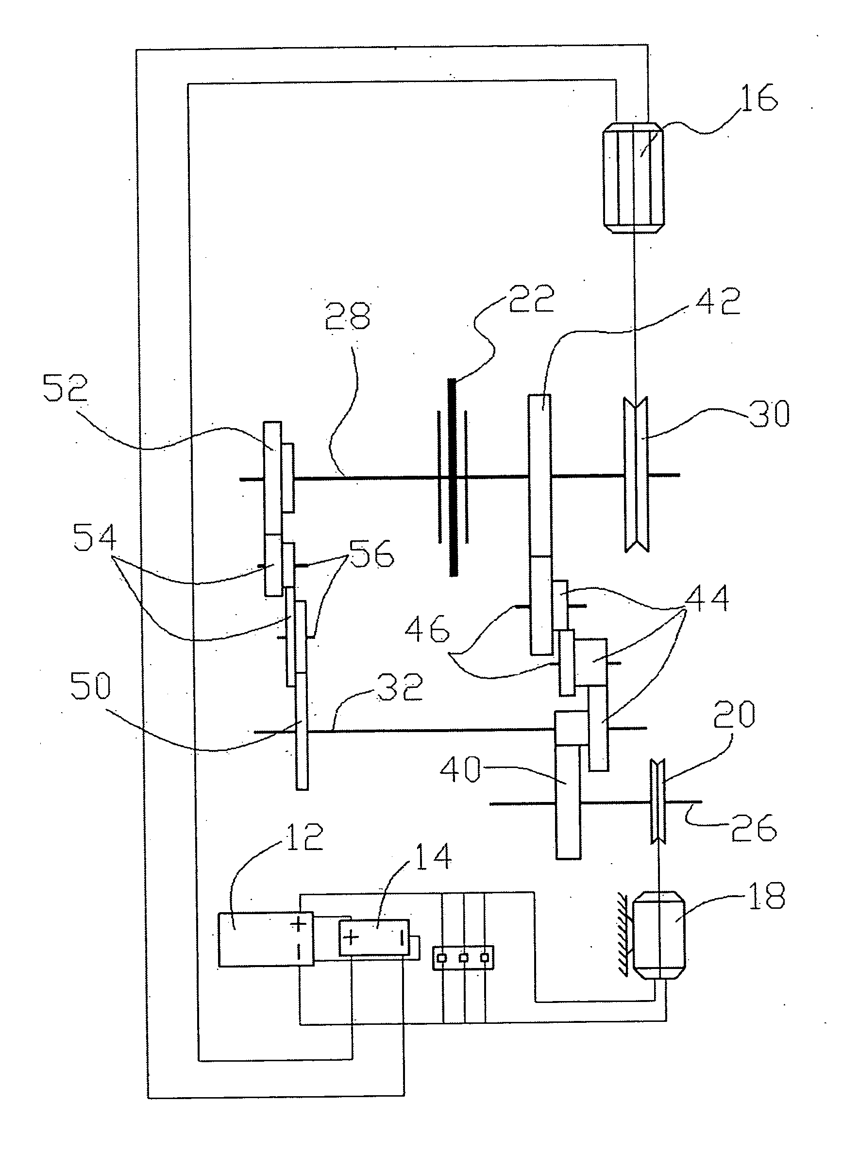
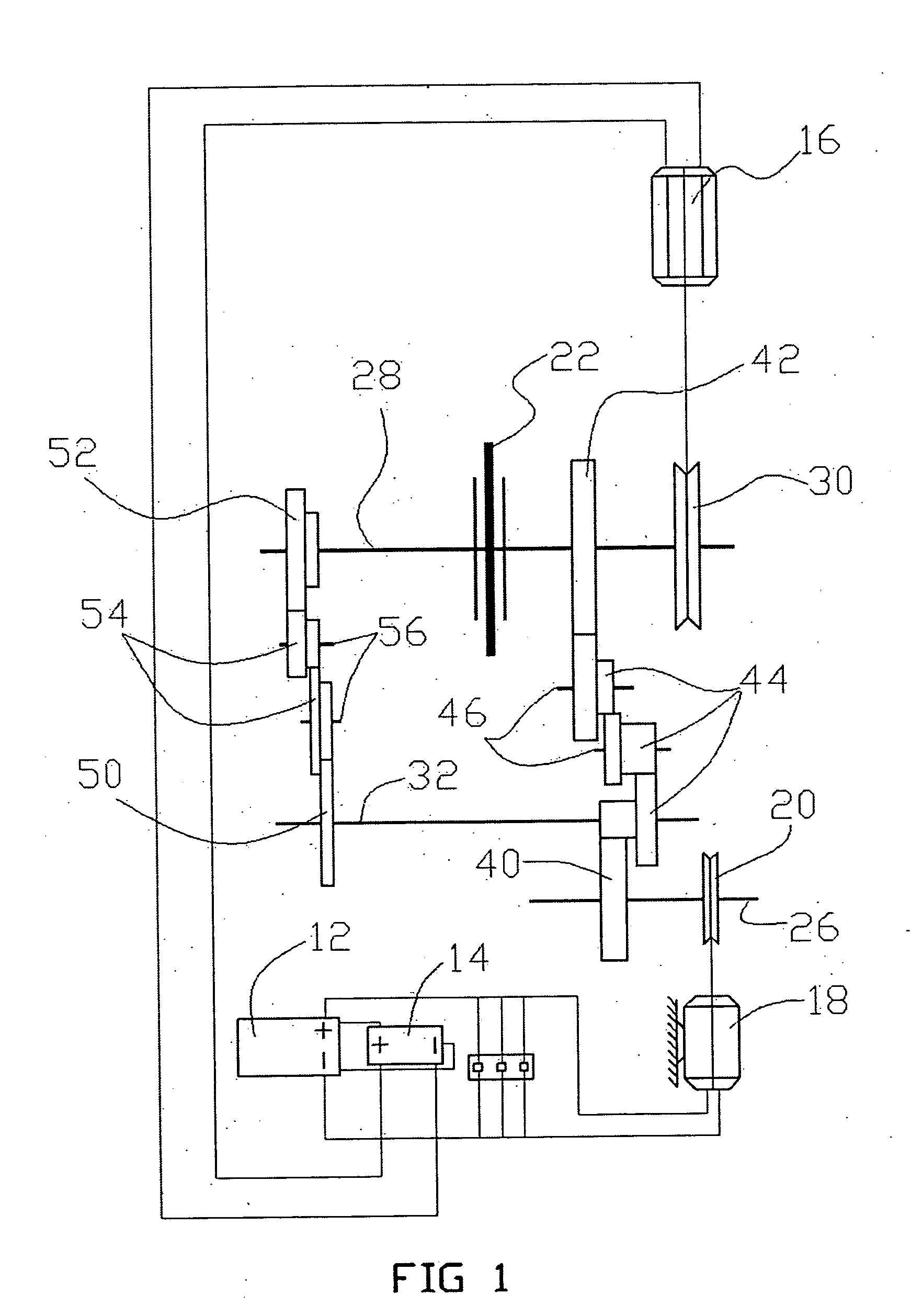
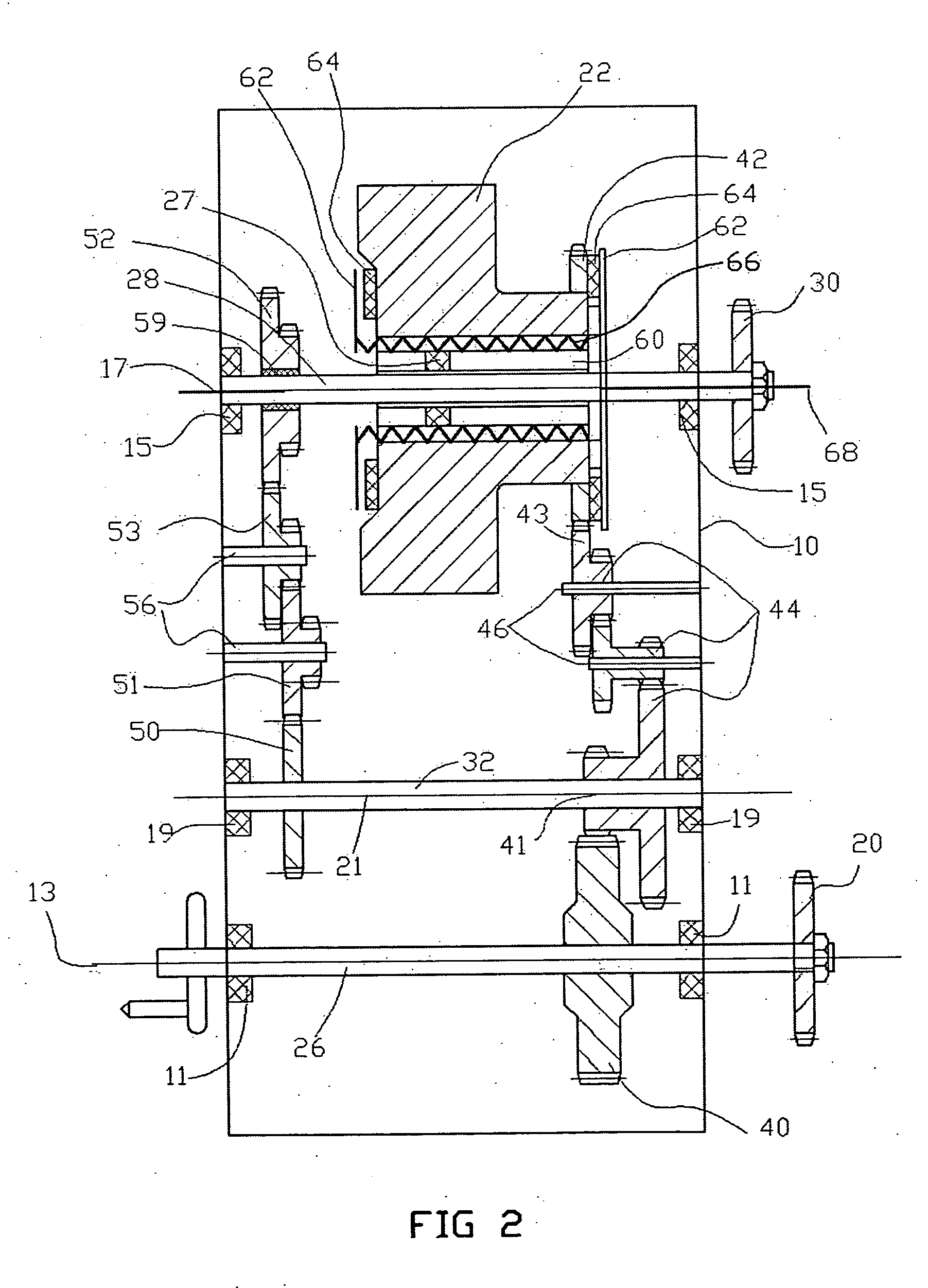
[0014] Referring initially to FIG. 1, a flywheel energy storage system in accordance with a preferred embodiment of the present invention comprises a frame 10 (shown in FIG. 2), a storage battery 12, a battery charger 14, an electric generator 16, an electric motor 18, a driving wheel 20, a flywheel 22, a driven wheel 30 and a transmission gear train assembly (not labeled).

[0015] The storage battery 12 is provided for supplying power to the electric motor 18 or customer's loads. The battery charger 14 is electrically connected to the storage battery 12 for charging the storage battery 12. The electric motor 18 is provided for driving the driving wheel 20.

[0016] With reference to FIG. 2, a driving shaft 26 is coupled to the frame 10. Opposite ends of the driving shaft 26 are engaged with and supported by two bearings 11 mounted on the frame 10. The driving shaft 26 is elongated along and ...


PUM


Abstract

A flywheel energy storage system includes a driving wheel rotatable relative to a first axis; an electric motor for driving the driving wheel; an electric generator; a driven wheel adapted to drive the electric generator; a flywheel rotatable relative to a second axis parallel to the first axis; a clutch assembly for engagement or disengagement of the flywheel and the driven wheel; and a transmission gear train assembly engagingly interposed between the flywheel and the driving wheel adapted for conveying kinetic energy from the driving wheel to the flywheel. The transmission gear assembly is provided for allowing the flywheel driven by a low-powered electric motor to drive a high-powered electric generator.

Description

BACKGROUND OF THE INVENTION [0001] 1. Field of the Invention [0002] The present invention relates to flywheel energy storage systems, and more particularly to a flywheel energy storage system utilizing a transmission gear assembly for allowing an energy storage flywheel driven by a low-powered electric motor to drive a high-powered electric generator. [0003] 2. Description of Prior Art [0004] It is well known that a flywheel energy storage system is a mechanical device that converts electrical energy into kinetic energy and, when necessary, converts the kinetic energy back to electrical energy. In other words, it acts like a chemical battery but with many advantages when compared to a traditional chemical battery. Compared with traditional batteries, flywheel energy storage systems store energy very efficiently and have very high output potential and relatively long life. Furthermore, the flywheel energy storage systems are relatively unaffected by ambient temperatures. [0005] A con...

Claims


Application Information

Patent Timeline
Patent Type & Authority Applications(United States)
IPC IPC(8): B60K6/30B62M1/10F03G7/10H02K7/02
CPCB62M1/10
Inventor LIU, BENRONGZHOU, CHUNYUANLIU, PINGZHOU, JIE
Owner LIU BENRONG
Why Eureka
Try Eureka