Touch panel display system with illumination and detection provided from a single edge

a display system and touch panel technology, applied in the field of touch panel display system, to achieve the effect of accurate detection of user touch, less time consuming and laborious, and less cos

Inactive Publication Date: 2005-11-10
SMART TECH INC (CA)
View PDF19 Cites 270 Cited by
  • Summary
  • Abstract
  • Description
  • Claims
  • Application Information

AI Technical Summary

Benefits of technology

[0008] The present invention, in accordance with exemplary embodiments described herein, provides a touch panel display system with illumination and detection functionality provided from a single edge of the touch panel. This touch panel display system can accurately detect a user's touch (e.g., with a finger, stylus, or other object) on or near the touch panel, but is less expensive and less time consuming to

Problems solved by technology

Furthermore, the touch panel display system is not particularly sensitive to variations in surrounding ligh

Method used


Image

  • Touch panel display system with illumination and detection provided from a single edge
  • Touch panel display system with illumination and detection provided from a single edge
  • Touch panel display system with illumination and detection provided from a single edge

Examples


Embodiment Construction

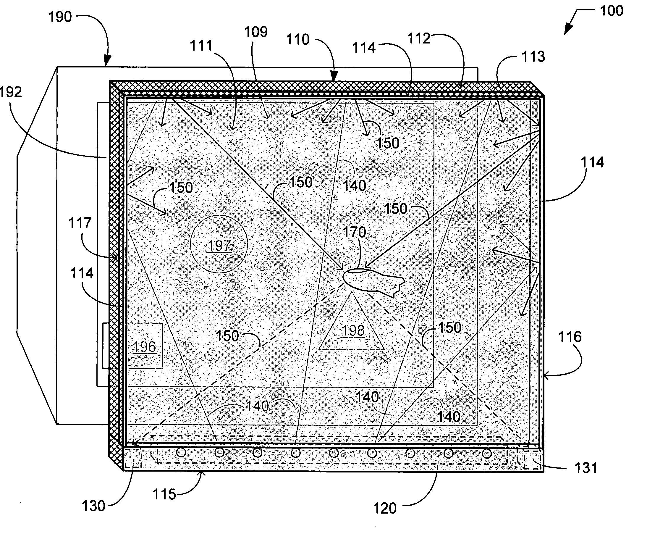
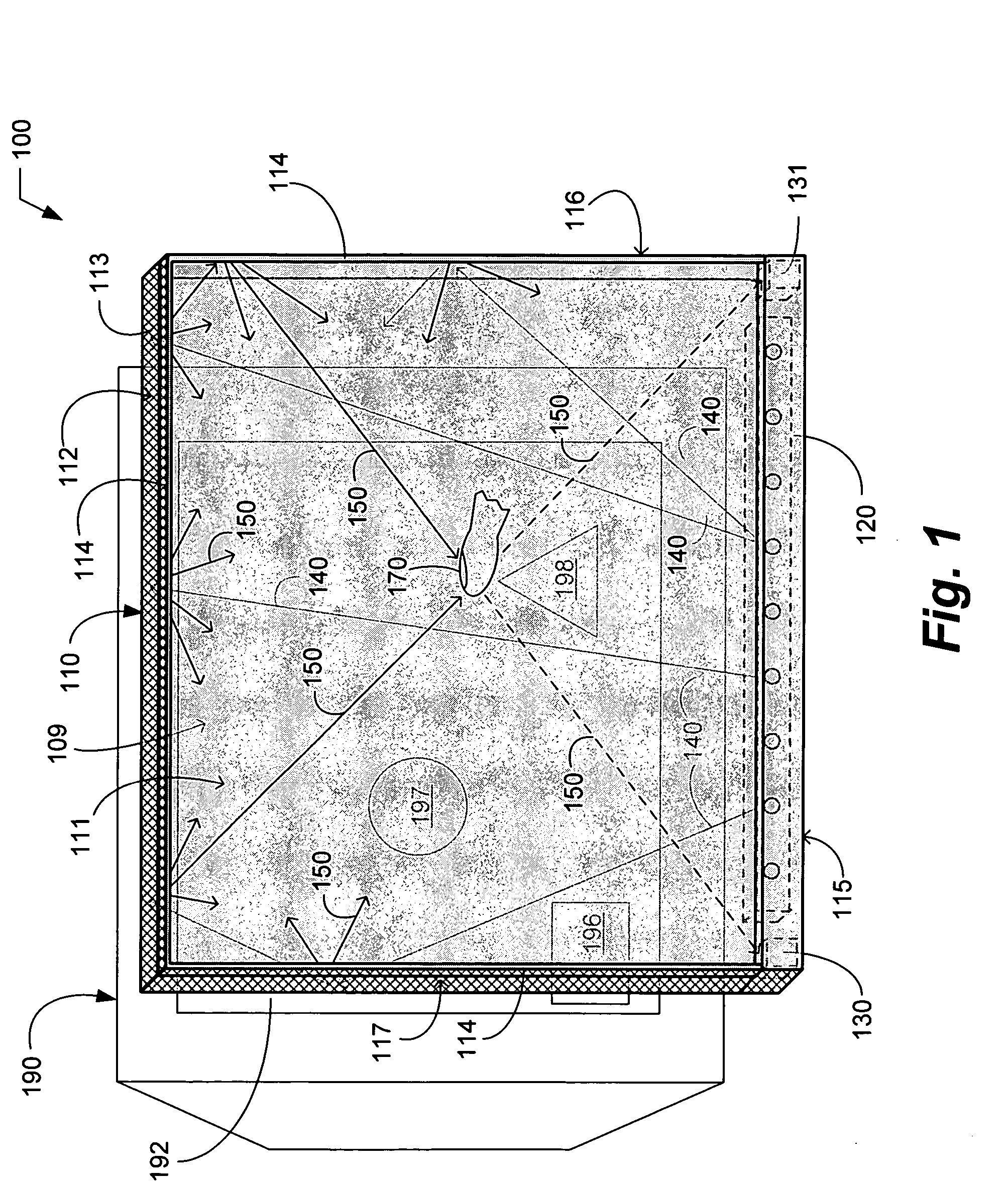
[0019] Exemplary embodiments of the present invention will hereinafter be described with reference to the drawings, in which like reference numerals represent like elements throughout the several figures. FIG. 1 is an exemplary perspective view of a touch panel display system 100 in accordance with an exemplary embodiment of the present invention. As used herein, the term “touch panel display system” is meant to refer to a touch panel 110 and the hardware and / or software components that provide touch detection functionality. A touch panel display system 100 is also commonly referred to as a touch screen system.

[0020] The exemplary touch panel display system 100 is shown adjacent to an exemplary display device (i.e., video monitor) 190. The display device 190 may be interfaced to a personal computer (not shown), which may execute software for detecting touches on or near the touch panel 110. The illustration in FIG. 1 of the touch panel display system 100 adjacent to the display dev...


PUM


Abstract

A touch panel that has a front surface, a rear surface, a plurality of edges and an interior volume. An energy source is positioned in proximity to a first edge of the touch panel and is configured to emit energy that is propagated within the interior volume of the touch panel. A diffusing reflector is positioned in proximity to the front surface of the touch panel for diffusively reflecting at least a portion of the energy that escapes from the interior volume. At least one detector is positioned in proximity to the first edge of the touch panel and is configured to detect intensity levels of the energy that is diffusively reflected across the front surface of the touch panel. Preferably, two detectors are spaced apart from each other in proximity to the first edge of the touch panel, to allow calculation of touch locations using simple triangulation techniques.

Description

TECHNICAL FIELD [0001] The present invention relates generally to a touch panel display system that allows a user to interact with displayed information by touching on or near a surface of the system. More particularly, the present invention relates to a touch panel display system that includes an energy source and a detector positioned on a single side of the touch panel, whereby a surface of the touch panel is illuminated by the energy source and an interruption of the illumination by a touch on or near the surface of the touch panel is detected by the detector. BACKGROUND OF INVENTION [0002] Touch panel display systems (also commonly known, for example, as touch screens systems) can allow a user to touch on or near an area of a touch panel (also commonly referred to as a touch screen) to enter a command to a computer system and, thereby, control the operation of the computer system. Touch panel display systems can provide an intuitive method by which people can easily interact wi...

Claims


Application Information

Patent Timeline
IPC IPC(8): G06F3/042G09G5/00
CPCG06F3/0436G06F3/0421
Inventor NEWTON, JOHN
Owner SMART TECH INC (CA)
Why Eureka
Try Eureka