
System and method for displaying the effects of light illumination on a surface

a technology of light illumination and surface, applied in the field of computer graphics, can solve the problems of not performing all processing actions for creating images, affecting the quality of the image,

Active Publication Date: 2005-11-10
VALVE
View PDF9 Cites 19 Cited by
  • Summary
  • Abstract
  • Description
  • Claims
  • Application Information

AI Technical Summary

Problems solved by technology

As a result, dynamic graphics require a considerable amount of processing power.
However, not all processing actions for creating an image may be performed at the preprocessing stage.
Shapes that have a high surface detail present a significant difficulty, as they may require a large number of polygons.
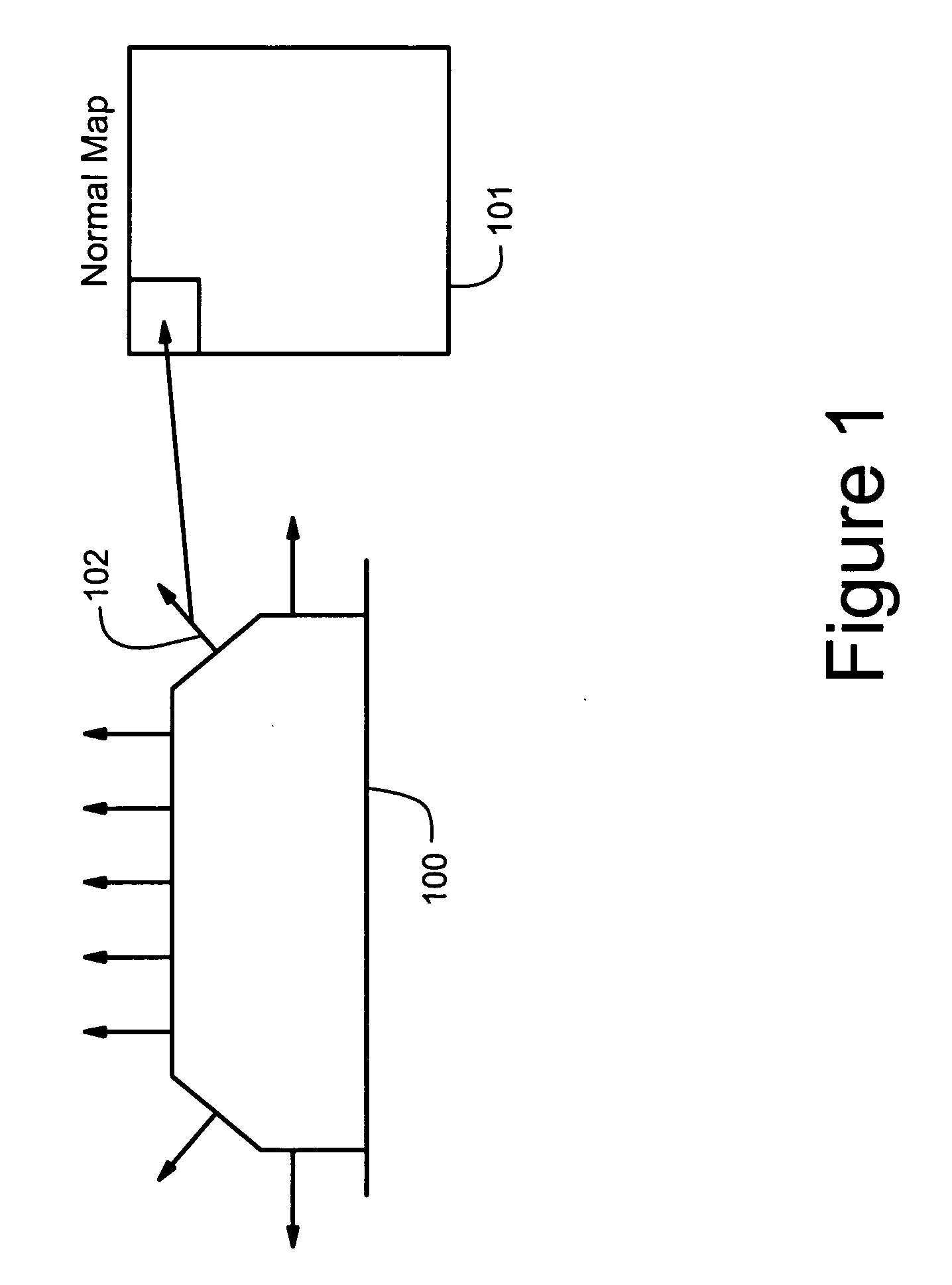
While a brick does have three dimensional aspects, especially around the edges, these may not be kept track of by the computer.
However, a two dimensional picture does not always provide a good representation of the three dimensional brick.
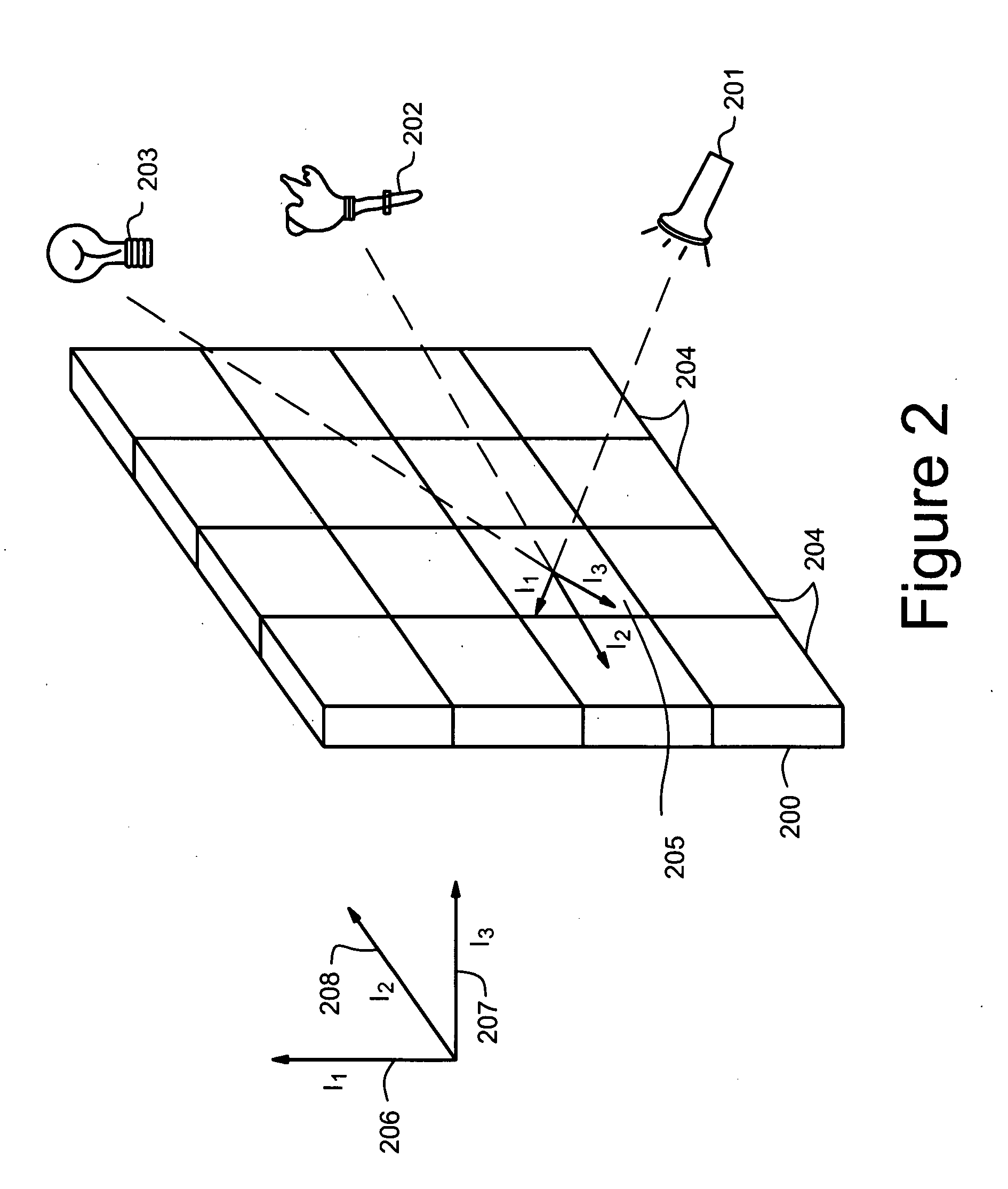
Environments that include a plurality of light sources are especially difficult to simulate in computer graphics.
This difficulty is magnified if the simulation must be done in real-time.
Furthermore, these relationships cannot be easily simplified.
For example, it is difficult to combine the effects of the multiple light sources into a single representative light source, which can be used for all surfaces, because the combined effects of multiple light sources differ greatly depending on the spatial relationship between the surface and the light sources.

Method used


Image

  • System and method for displaying the effects of light illumination on a surface
  • System and method for displaying the effects of light illumination on a surface
  • System and method for displaying the effects of light illumination on a surface

Examples


Embodiment Construction

[0021] The present invention now will be described more fully hereinafter with reference to the accompanying drawings, which form a part hereof, and which show, by way of illustration, specific exemplary embodiments by which the invention may be practiced. This invention may, however, be embodied in many different forms and should not be construed as limited to the embodiments set forth herein; rather, these embodiments are provided so that this disclosure will be thorough and complete, and will fully convey the scope of the invention to those skilled in the art. Among other things, the present invention may be embodied as methods or devices. Accordingly, the present invention may take the form of an entirely hardware embodiment, an entirely software embodiment or an embodiment combining software and hardware aspects. The following detailed description is, therefore, not to be taken in a limiting sense.

[0022] Some of the difficulties of displaying three dimensional objects describe...


PUM


Abstract

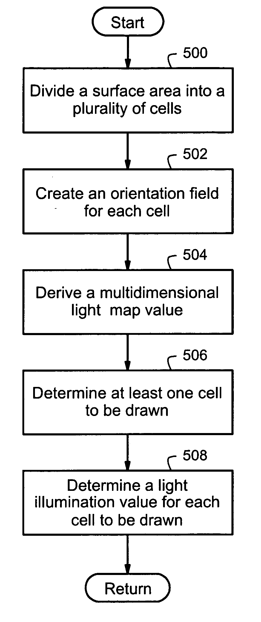
Provided is a system and method for displaying the effects of light illumination on a surface. One or more light sources are illuminating a surface. The surface is divided into one or more cells. The orientation of each cell is determined and saved in an orientation field. A multidimensional light map value is derived and associated with the surface. The multidimensional light map value defines the combined illumination of the one or more light sources on the surface, and may optionally be a vector. At least one cell to be drawn is determined. For each cell to be drawn, an illumination value associated with that cell to be drawn is determined. The illumination value is based on the orientation field and the multidimensional light map value. The illumination value may be the dot product of the orientation field and the multidimensional light map value.

Description

FIELD OF THE INVENTION [0001] This application relates generally to computer graphics and specifically to determining and displaying light illumination effects on a surface. BACKGROUND OF THE INVENTION [0002] It has long been the goal of the computer arts to create compelling visual images through computer graphics. While these visual images may represent real or imaginary things, they still require that certain aspects be presented with high realism. This requirement is especially true for optics. Humans rely on light to perceive the world around them. Variations in light due to various optical interactions are decoded by our brains into information about the nature, position shape and relationship between objects in the world. For this reason, any representation in computer graphics whether realistic or fantastic requires a certain amount of optical realism in order to be properly evaluated by the human brain. [0003] Since we live in and perceive a three dimensional world, three d...

Claims


Application Information

Patent Timeline
IPC IPC(8): G06T15/50G06T15/60G06T17/00
CPCG06T15/506G06T15/50
Inventor MCTAGGART, GARY M.
Owner VALVE
Learn More