
Fingerprint Correction Method Based on Orientation Field Distribution

A correction method and technology of direction field, applied in the acquisition/organization of fingerprints/palmprints, matching and classification, instruments, etc., can solve the problems of inability to estimate the direction and center of fingerprints, unable to detect fingerprints, not vertical, etc.

Active Publication Date: 2015-07-29
TSINGHUA UNIV
View PDF3 Cites 2 Cited by
  • Summary
  • Abstract
  • Description
  • Claims
  • Application Information

AI Technical Summary

Problems solved by technology

This process is very tedious and time-consuming
On the other hand, when collecting live fingerprints (including various fingerprint recognition applications including public security and civilian use), it is easy to produce fingerprints with non-standard collection postures, that is, the pressed position of the collected fingerprints is not in the center of the image, and the angle is not vertical
To identify these fingerprints with non-standard postures, the fingerprint matching algorithm has to consider various possible spatial transformations, resulting in high computational complexity
[0004] What the present invention aims to solve is the problem of automatic detection and correction of fingerprints under non-standard acquisition postures and complex backgrounds
Existing techniques mainly segment fingerprint regions based on local features such as gray-level variance and gray-level gradient consistency. These features have good performance when the image background is clean, but have little effect when the background is complex, and they can only estimate Whether the local area of ​​the image is a fingerprint, the orientation and center of the entire fingerprint cannot be estimated, and therefore it is impossible to correct a fingerprint with an incorrect pose, and it is impossible to detect a fingerprint from a low-quality crime scene fingerprint
Due to the deficiencies of the existing technology, in the manned fingerprint identification system, the detection and correction of fingerprints are usually done manually by the staff, which is time-consuming and laborious.
In an unattended fingerprint recognition system, fingerprints with incorrect poses can only be solved by fingerprint matching algorithms, which has high computational complexity and easily leads to wrong matches

Method used


Image

  • Fingerprint Correction Method Based on Orientation Field Distribution
  • Fingerprint Correction Method Based on Orientation Field Distribution
  • Fingerprint Correction Method Based on Orientation Field Distribution

Examples


Embodiment Construction

[0025] Embodiments of the present invention are described in detail below, examples of which are shown in the drawings, wherein the same or similar reference numerals designate the same or similar elements or elements having the same or similar functions throughout. The embodiments described below by referring to the figures are exemplary and are intended to explain the present invention and should not be construed as limiting the present invention.

[0026] In describing the present invention, it should be understood that the terms "center", "longitudinal", "transverse", "length", "width", "thickness", "upper", "lower", "front", " Orientation or position indicated by "back", "left", "right", "vertical", "horizontal", "top", "bottom", "inner", "outer", "clockwise", "counterclockwise", etc. The relationship is based on the orientation or positional relationship shown in the drawings, and is only for the convenience of describing the present invention and simplifying the descrip...


PUM


Abstract

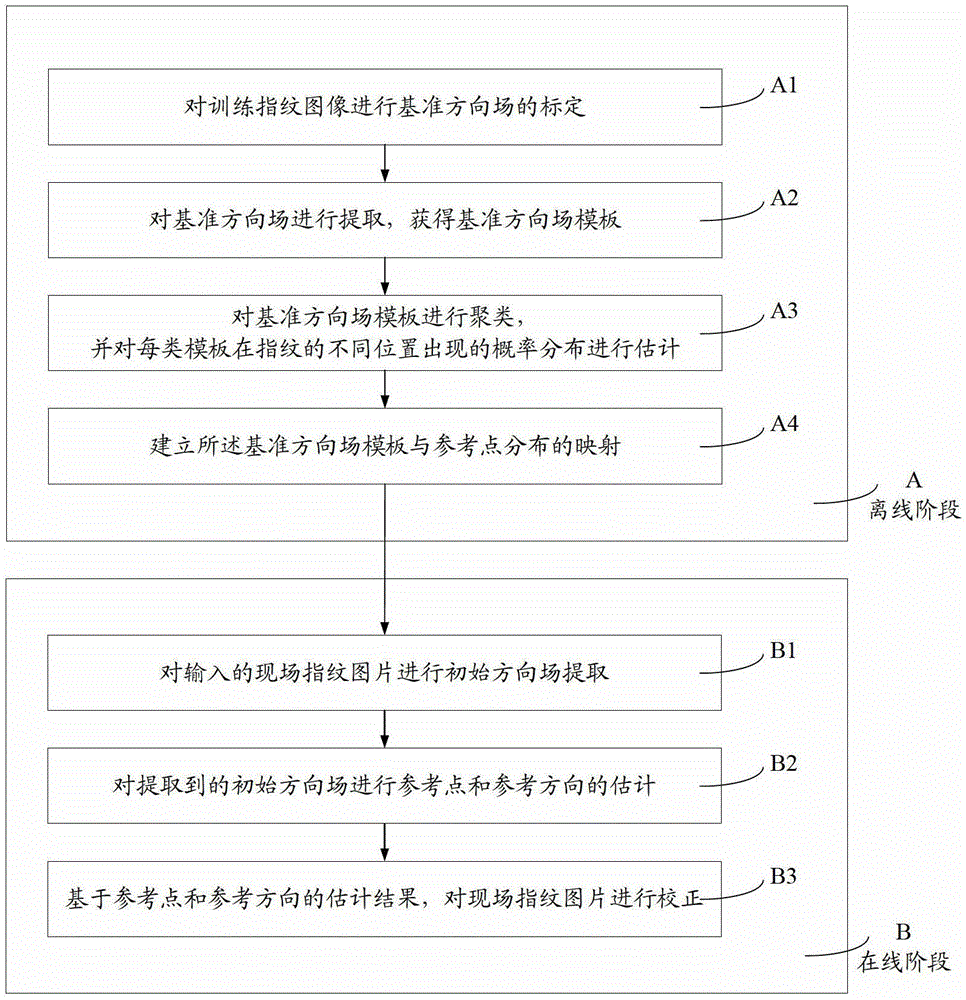
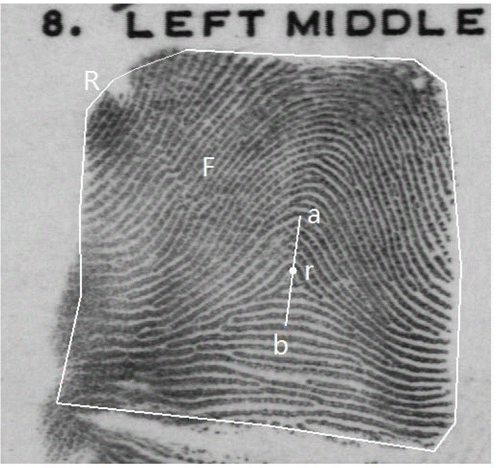
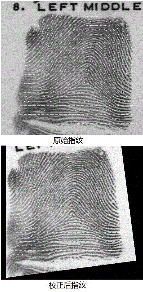
A method for registering a fingerprint image is provided. The method comprises steps of: establishing an orientation field template base according to M training fingerprints, wherein M is a positive integer larger than one; receiving a fingerprint image to be registered; obtaining an initial orientation field of the fingerprint image; obtaining an estimated position and an estimated direction of the fingerprint image according to the initial orientation field and the orientation field template base; and registering the fingerprint image according to a preset position, a preset direction, the estimated position and the estimated direction.

Description

technical field [0001] The invention relates to the field of fingerprint identification, in particular to a fingerprint correction method based on direction field distribution. Background technique [0002] Due to the important properties of fingerprints such as uniqueness, universality and lifetime invariance, the use of fingerprint images for identification has a long history. In the field of public security criminal investigation, since the early 20th century, fingerprints have gradually become one of the most important evidences for law enforcement agencies to arrest and convict criminals. In recent years, the development and maturity of automatic fingerprint recognition technology has made fingerprint recognition widely used in public security criminal investigation, entry and exit, access control systems and authority control of important equipment. [0003] In the field of public security criminal investigation, the main object of fingerprint identification is the fi...

Claims


Application Information

Patent Timeline
Patent Type & Authority Patents(China)
IPC IPC(8): G06K9/00G06K9/62
CPCG06K9/00087G06K9/00067G06K9/0008G06V40/1359G06V40/1365G06V40/1347
Inventor 周杰冯建江杨霄
Owner TSINGHUA UNIV
Learn More