Injet printhead having externally-connected terminations structured to be resistant to damage

a technology of inkjet printheads and terminations, applied in printing and other directions, can solve problems such as electrical disconnection

Active Publication Date: 2005-11-10
BROTHER KOGYO KK
View PDF8 Cites 54 Cited by
  • Summary
  • Abstract
  • Description
  • Claims
  • Application Information

AI Technical Summary

Benefits of technology

[0025] It is therefore an object of the present invention to provide a structure employed in an inkjet printhead for externally and electrically connecting the inkjet printhead, with an improved resistance to damage causing undesired electrical disconnection.
[0041] Therefore, the inkjet printhead according to the present invention allows the connection portion between the corresponding inner conductive electrode and the corresponding surface electrode to be protected from being damaged.
[0042] Further, in the inkjet printhead according to the present invention, each external conductive area is formed on the top sheet so as to be tightly joined to the corresponding through hole at its open end, thereby allowing delicate sites of the connection portion between the corresponding inner conductive electrode and the corresponding surface electrode to be protected from being damaged, in an ensured fashion.

Problems solved by technology

However, the following drawbacks are encountered in manufacturing the conventional inkjet printheads described above.
As a result, for the conventional inkjet printheads, the possibility arises that the connection portion chips or peels off from the uppermost layer during handling of the actuator, resulting in electrical disconnection.

Method used


Image

  • Injet printhead having externally-connected terminations structured to be resistant to damage
  • Injet printhead having externally-connected terminations structured to be resistant to damage
  • Injet printhead having externally-connected terminations structured to be resistant to damage

Examples


first embodiment

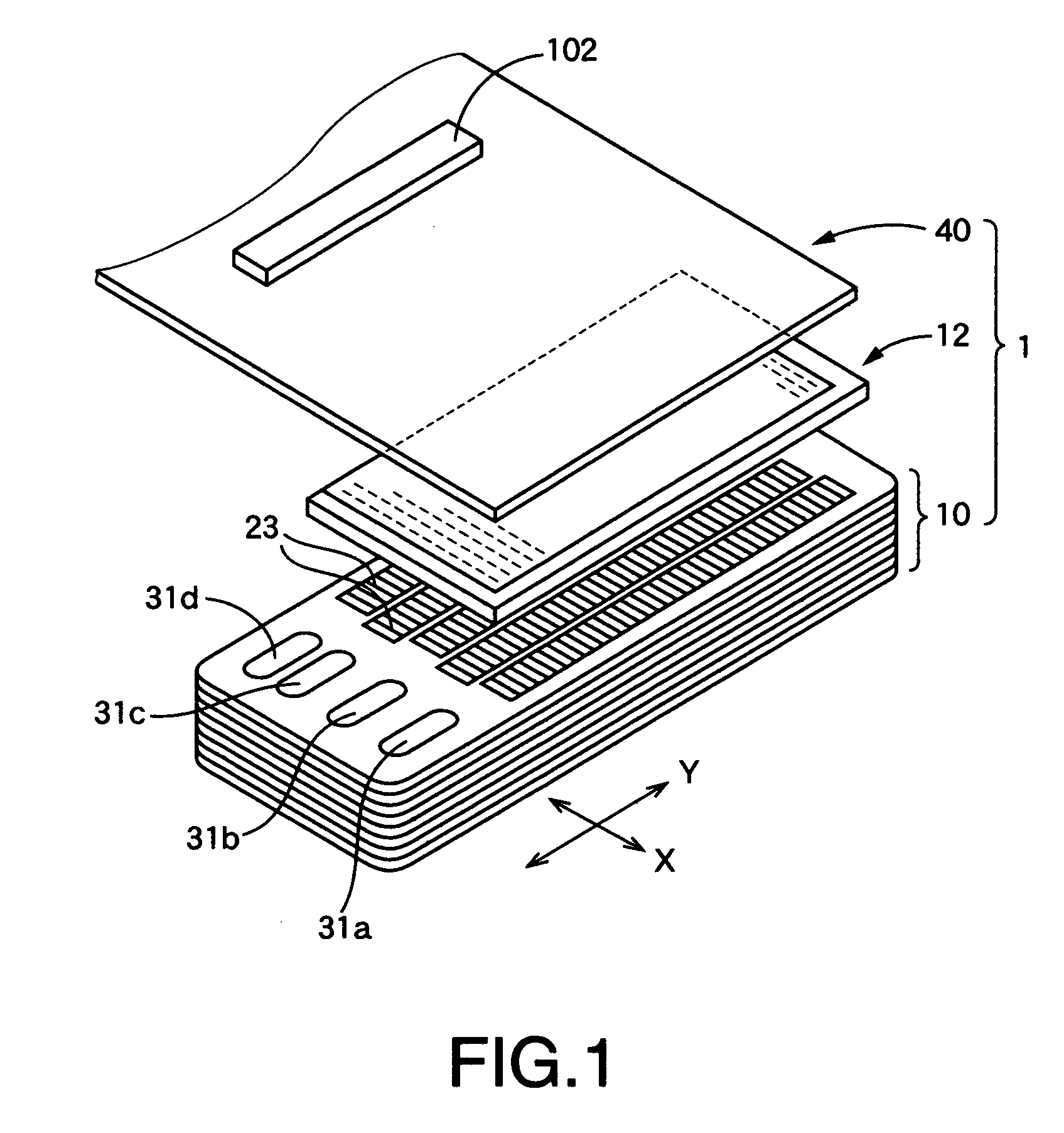
[0123]FIG. 1 shows in exploded perspective view a head unit 1 of an inkjet printhead for color printing in accordance with the present invention.

[0124] The inkjet printhead, as is known in the art, is mounted on a carriage (not shown) reciprocally moved in a direction (a primary scanning direction, hereinafter referred to as “second direction” or “X-direction”) perpendicular to a direction (a secondary scanning direction, hereinafter referred to as “first direction” or “Y-direction) in which a sheet (not shown) is fed to be printed in a printer (not shown) constructed as an image forming apparatus.

[0125] The inkjet printhead includes a head holder (not shown) mounted on the carriage, which holds the head unit 1 facing a print face of the aforementioned sheet.

[0126] The image forming apparatus uses an ink cartridge (not shown) which is adapted to be filled with different colored ink, for example, four different colored ink of Cyan, Magenta, Yellow, and Black, on a color-by-color ba...


PUM


Abstract

An inkjet printhead is disclosed which includes nozzles for ejecting ink droplets; a cavity unit incorporating pressure chambers; and an actuator in the form of a laminate of sheets. The actuator includes individual electrodes and a top sheet having bonding terminations. The inkjet printhead is bonded at the bonding terminations to a flexible flat cable. The bonding terminations include surface electrodes formed on the top sheet. The top sheet includes through holes, each of which is filled with a conductive material locally communicated with a corresponding one of the surface electrodes at a communication portion thereof. The top sheet includes external conductive areas, each formed on a surface of a corresponding one of the surface electrodes, and each having a thickness larger than that of the corresponding surface electrode. Each of the external conductive areas overlays an open end of the corresponding through hole located in the communication portion.

Description

[0001] This application is based on Japanese Patent Applications No. 2004-015494 filed 23 Jan., 2004, and No. 2004-193885 filed 30 Jun., 2004, and U.S. Utility patent application Ser. No. 11 / 040,744 filed Jan. 21, 2005, the contents of which are incorporated hereinto by reference. CROSS-REFERENCE TO RELATED APPLICATIONS [0002] This is a continuation-in-part application of application Ser. No. 11 / 040,744 filed Jan. 21, 2005, now pending.BACKGROUND OF THE INVENTION [0003] 1. Field of the Invention [0004] The invention relates to a structure employed in an inkjet printhead for externally and electrically connecting the inkjet printhead, and more particularly to bonding terminations of an inkjet printhead having an actuator, wherein the bonding terminations are formed on the surface of the actuator for allowing its electrical connection with a flexible flat cable for use in transmission of control signals. [0005] 2. Description of the Related Art [0006] Various types of inkjet printhead...

Claims


Application Information

Patent Timeline
Patent Type & Authority Applications(United States)
IPC IPC(8): B41J2/045B41J2/14
CPCB41J2/14209B41J2002/14491B41J2002/14225B41J2002/14217
Inventor ISONO, JUN
Owner BROTHER KOGYO KK
Why Eureka
Try Eureka