Fluid filtration apparatus and method

a filter apparatus and fluid technology, applied in the direction of moving filter element filters, filtration separation, separation processes, etc., can solve the problems of unfavorable production and production costs of filter apparatus, and the complexity of such filters tends to drive up the price of filter apparatus and the cost of production. , to achieve the effect of less pressure drop through the filter apparatus

Inactive Publication Date: 2005-11-17
FUJIFILM HEALTHCARE CORP +1
View PDF49 Cites 19 Cited by
  • Summary
  • Abstract
  • Description
  • Claims
  • Application Information

AI Technical Summary

Benefits of technology

[0020] In one form of the invention, the full flow restrictor, full flow media, equivalent bypass orifice, and bypass filter media are cooperatively configured in such a manner that, at the operating temperature, the flow of fluid through the full flow filter will be larger than the flow of fluid through the bypass filter, and at a predetermined temperature below the operating temperature, the flow of fluid through the bypass filter will be larger than the flow of fluid through the full flow filter. Because the bypass filter media is less restrictive than the full flow filter media, this configuration results in less pressure drop through the filter apparatus, in comparison to prior filter apparatuses, during periods where the fluid is relatively cold, such as when an engine is first started and the engine lubricating oil has not yet come up to operating temperature.

Problems solved by technology

Although prior filters, using venturi tubes to draw a small percentage of the total fluid being filtered through a higher efficiency bypass filter, generally work well for their intended purpose, certain drawbacks have been noted.
It can thus take some time before all of the fluid passes through the bypass filter.
It has been noted that the media in such filters tends to capture contaminant particles in a non-uniform manner, which tends to reduce the amount of contaminant that the filter can remove and hold, before the pressure drop through the filter apparatus rises to a point that the filter should be replaced.
The complexity of such filters also tends to undesirably drive up the cost of production and the price of the filter apparatus.

Method used


Image

  • Fluid filtration apparatus and method
  • Fluid filtration apparatus and method
  • Fluid filtration apparatus and method

Examples


Embodiment Construction

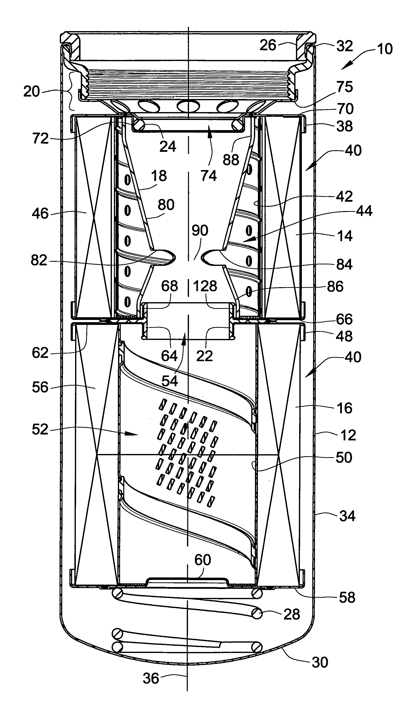
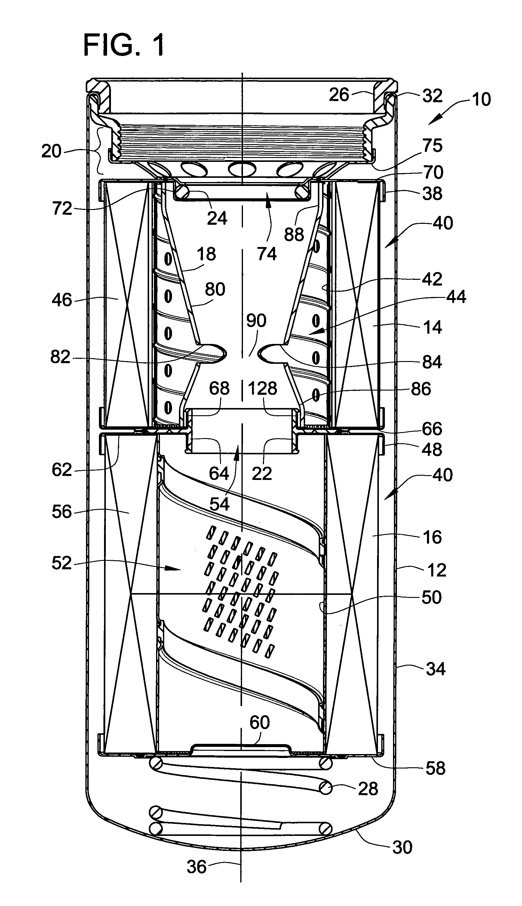
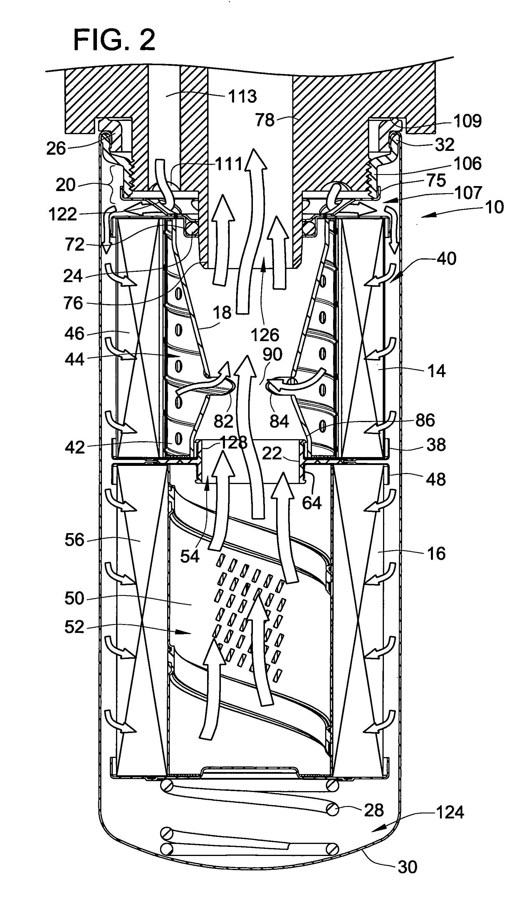
[0032]FIGS. 1 through 3 show a first exemplary embodiment of a filter apparatus, according to the invention, in the form of a spin-on filter 10. As shown in FIG. 1, the spin on filter 10 includes, a housing 12, enclosing a bypass filter 14, a full flow filter 16, a flow balancing element 18, a baseplate and spacer apparatus 20, an intermediate seal 22, an outlet seal 24, an inlet seal 26, and a helical compression spring 28. In general, FIGS. 1 and 3 show structural details of the exemplary embodiment of the spin-on filter 10, and FIG. 2 shows the manner in which fluid flows through the exemplary embodiment of the spin-on filter 10.

[0033] The housing 12 has a closed end 30 and an open end 32, joined by a cylindrical sidewall 34 defining a longitudinal axis 36 extending from the closed end 30 to the open end 32 of the housing 12.

[0034] The bypass filter 14 is disposed within the housing 12 at a point along the longitudinal axis 36 adjacent the open end 32 of the housing 12. The byp...


PUM

PropertyMeasurementUnit
sizeaaaaaaaaaa
sizeaaaaaaaaaa
operating temperatureaaaaaaaaaa

Abstract

An apparatus and method for filtering a liquid utilize a filter apparatus including a bypass filter, a full flow filter, and a flow balancing element for dividing a total inlet flow of fluid to the filter apparatus into a bypass portion, passing through the bypass filter, and a full flow portion, passing through the full flow filter. The bypass filter has a lower filtering efficiency than the full flow filter element, so that a venturi tube is not required for causing the bypass portion to pass through the bypass filter. The flow balancing element divides the flow into a desired bypass portion and a desired full flow portion, at a predetermined operating temperature. Below the operating temperature, the bypass portion increases and the full flow portion decreases, the bypass portion becoming greater that the full flow portion at a second predetermined temperature below the operating temperature.

Description

FIELD OF THE INVENTION [0001] This invention relates to an apparatus and method for filtering impurities from liquids, such as lubricating oil, hydraulic fluid and the like. More particularly, the invention relates to filtering impurities using a spin-on filter adapted to thread onto a filter mounting adaptor of, for example, a hydraulic system or a lubricating system. BACKGROUND OF THE INVENTION [0002] spin-on filter is designed for a specified service life. The filter is then discarded and replaced with a new filter. Typically, more than one manufacturer produces filters which are interchangeable. As a disposable or throw-away type of item, the decision to purchase one brand of filter over a different brand is often based substantially on the price of the filter, and how often it must be replaced. For filters providing lubrication oil to an engine which will need to be started at cold ambient temperatures, it is also important to select a filter that has a low flow resistance duri...

Claims


Application Information

Patent Timeline
Patent Type & Authority Applications(United States)
IPC IPC(8): B01D27/10
CPCB01D27/108B01D2201/0461B01D27/08Y10S210/17B01D2201/291B01D35/30B01D27/144B01D2201/208B01D2201/4038Y10S210/13B01D2201/188B01D35/147
Inventor FISHER, GREG
Owner FUJIFILM HEALTHCARE CORP
Why Eureka
Try Eureka