
Stator coil including sequentially connected segment conductors preferably applicable to an electric rotary machine

a technology of segment conductors and stator coils, which is applied in the direction of synchronous machines, windings, dynamo-electric components, etc., to achieve the effect of simplifying connection, simple layout of neutral bus bars, and convenient connection

Active Publication Date: 2005-11-17
DENSO CORP
View PDF11 Cites 62 Cited by
  • Summary
  • Abstract
  • Description
  • Claims
  • Application Information

AI Technical Summary

Benefits of technology

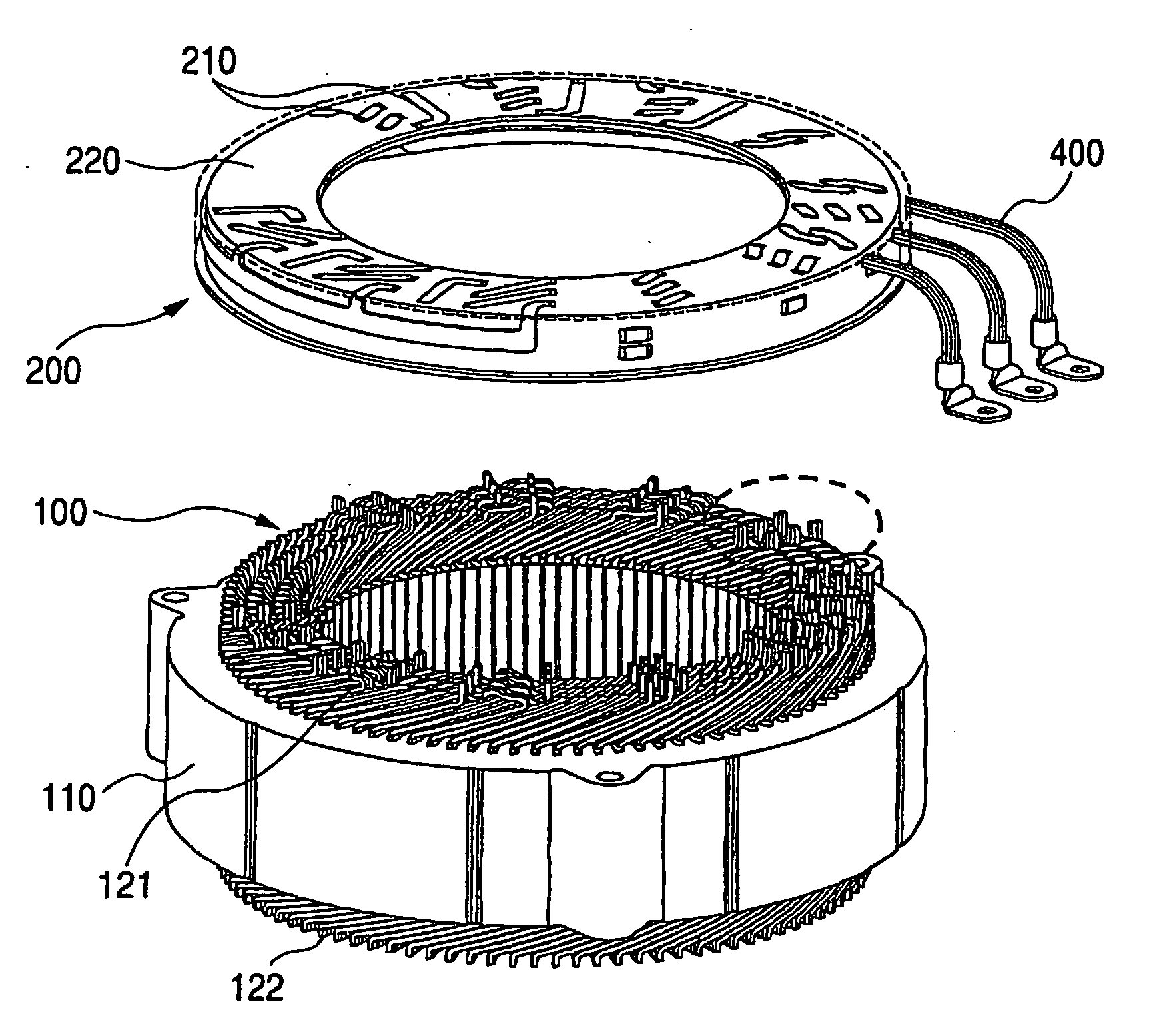
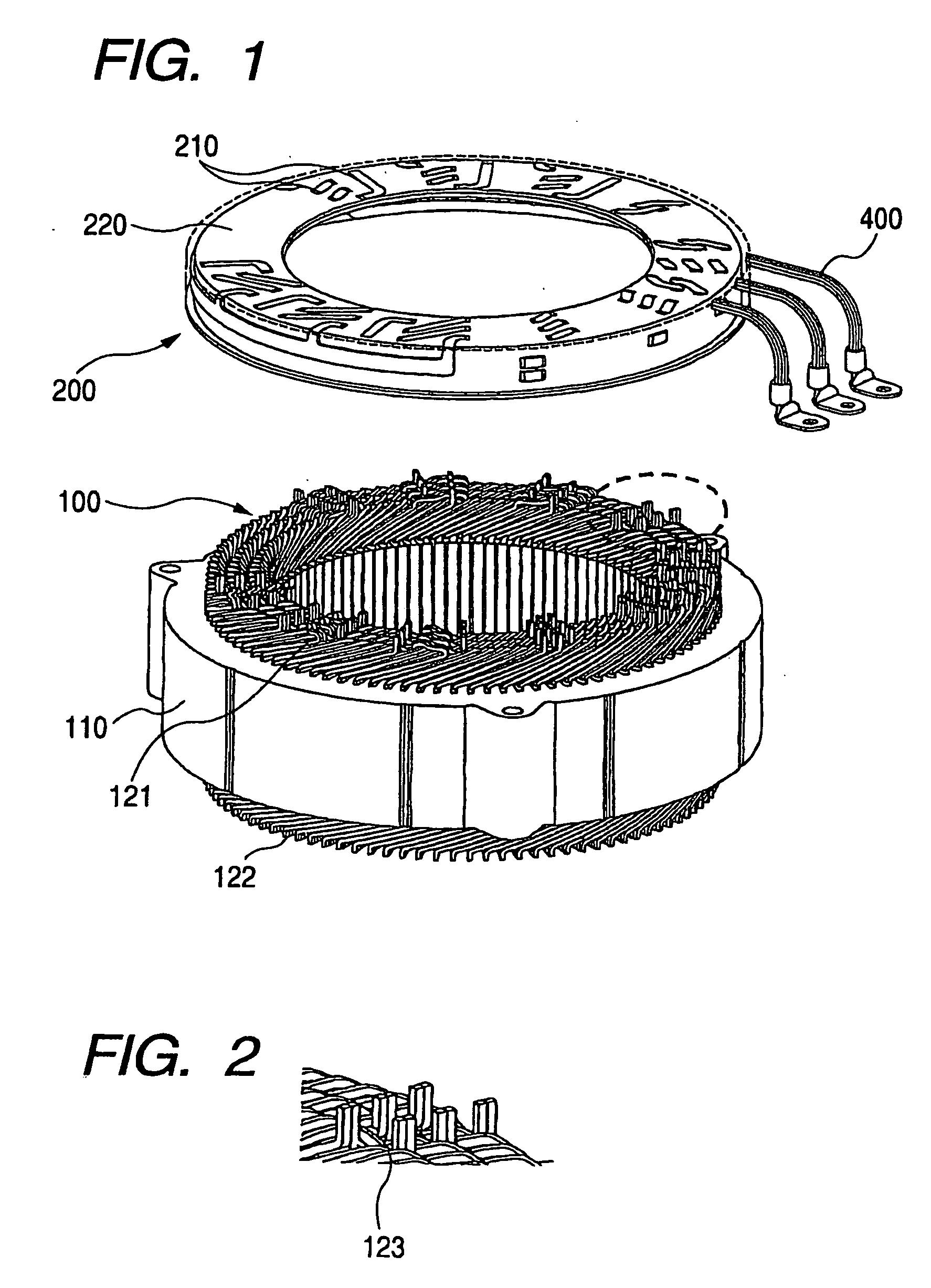
The present invention provides a stator coil with sequentially connected segment conductors that can be easily changed to change the wiring pattern. The stator coil includes a bus bar array board that integrates inter-group crossover bus bars with the insulating member, simplifying the work of connecting partial coils. The bus bar array board can be selected from multiple options and the serial turn number of one phase can be adjusted by changing the connecting pattern of the partial coils. The invention also simplifies the work of inserting and bending segment conductors, reduces wiring distance, and improves productivity.

Problems solved by technology

Furthermore, it is unnecessary to provide crossover wires of partial coils by elongating the segment conductor forming the end portion of a partial coil extending in the circumferential direction or the radial direction to connect the partial coils.

Method used


Image

  • Stator coil including sequentially connected segment conductors preferably applicable to an electric rotary machine
  • Stator coil including sequentially connected segment conductors preferably applicable to an electric rotary machine
  • Stator coil including sequentially connected segment conductors preferably applicable to an electric rotary machine

Examples


Embodiment Construction

[0029] Preferred embodiments of the present invention will be explained hereinafter with reference to attached drawings.

[0030] Hereinafter, a stator coil of the present invention will be explained with reference to the following preferred embodiments. However, the present invention is not limited to the following embodiments and accordingly can be modified in various ways within the scope of the present invention.

[0031] An electric rotary machine equipped with a stator coil including sequentially connected segment conductors in according to this embodiment has the same structure as that of an ordinary inner rotor type three-phase electric rotary machine. Accordingly, this electric rotary machine has a stator including a stator core and a stator coil. The stator core is fixed to an inner cylindrical surface of the housing of this rotary machine. The stator coil, wound around this stator core, includes sequentially connected segment conductors. A rotor, having magnetic poles at the ...


PUM


Abstract

A stator coil includes a coil portion wound around a stator core and a terminal board serving as a bus bar array board. The coil portion is arranged by sequentially connected segment conductors. The terminal board is a molded ring plate member disposed adjacently to a head coil end of the coil portion in the axial direction and elongated in the radial direction. The turn number of the stator coil is easily adjustable by selecting an optimum one of a plurality of terminal boards.

Description

CROSS-REFERENCE TO RELATED APPLICATION [0001] This application is based upon and claims the benefit of priority from earlier Japanese Patent Application No. 2004-145637 filed on May 14, 2004 so that the description of which is incorporated herein by reference. BACKGROUND OF THE INVENTION [0002] The present invention relates to a stator coil including sequentially connected segment conductors preferably applicable to an electric rotary machine. [0003] From the view point of providing compact automotive electric rotary machines and increasing the output of these machines, a stator coil including sequentially connected segment conductors is preferably employed for an electric rotary machine because this stator coil can reduce the size of the coil end (refer to the Japanese patent No. 3118837 or the Japanese patent application laid-open No. 2002-58189). [0004] For example, the Japanese patent No. 3118837 discloses a U-shaped segment (i.e. a rectangular conductor wire covered with insula...

Claims


Application Information

Patent Timeline
Patent Type & Authority Applications(United States)
IPC IPC(8): H02K3/04H02K1/00H02K3/12H02K3/28H02K3/50H02K11/00H02K15/085H02K19/26
CPCH02K3/12H02K2203/09H02K3/50H02K3/28
Inventor SEGUCHI, MASAHIROKOUDA, SHINJI
Owner DENSO CORP
Learn More