

Electric actuator
a technology of electric actuators and actuators, applied in the direction of resistance electrode holders, mechanical devices, gearing, etc., can solve the problems of significant maintenance and other costs, inherently embodied limitations, and concern of worksite contamination, etc., and achieve the effect of sacrificing size or weight restrictions, and reducing the risk of contamination
- Summary
- Abstract
- Description
- Claims
- Application Information
AI Technical Summary
Benefits of technology
Problems solved by technology
Method used
Image

Examples
Embodiment Construction
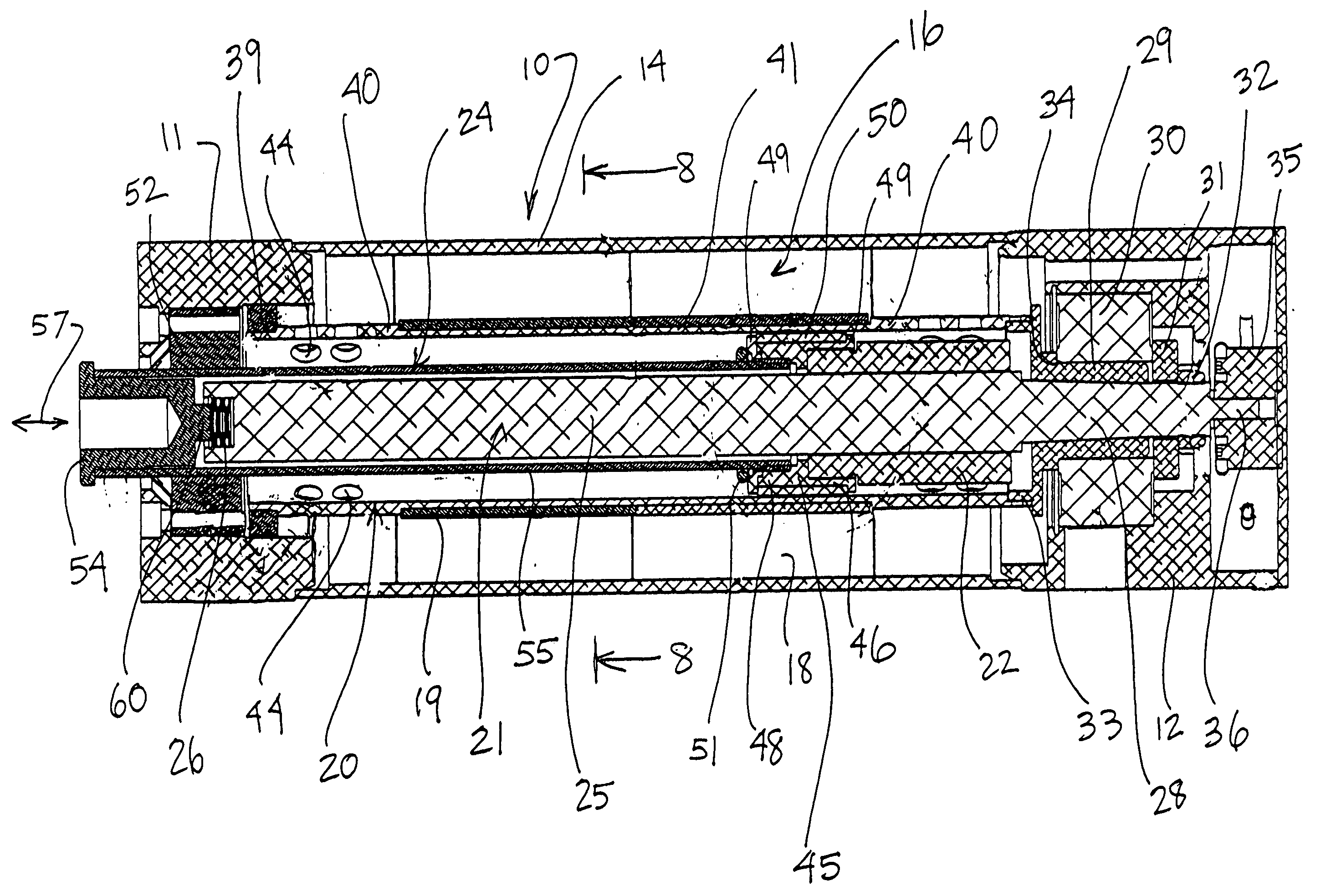
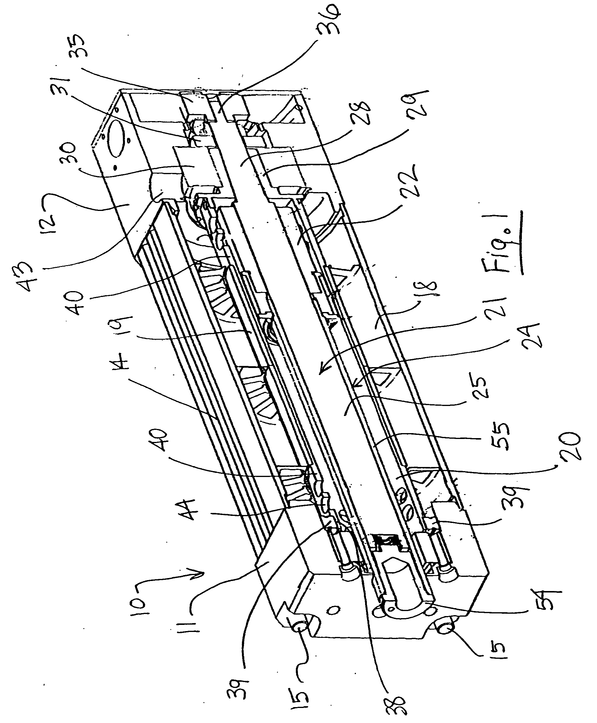
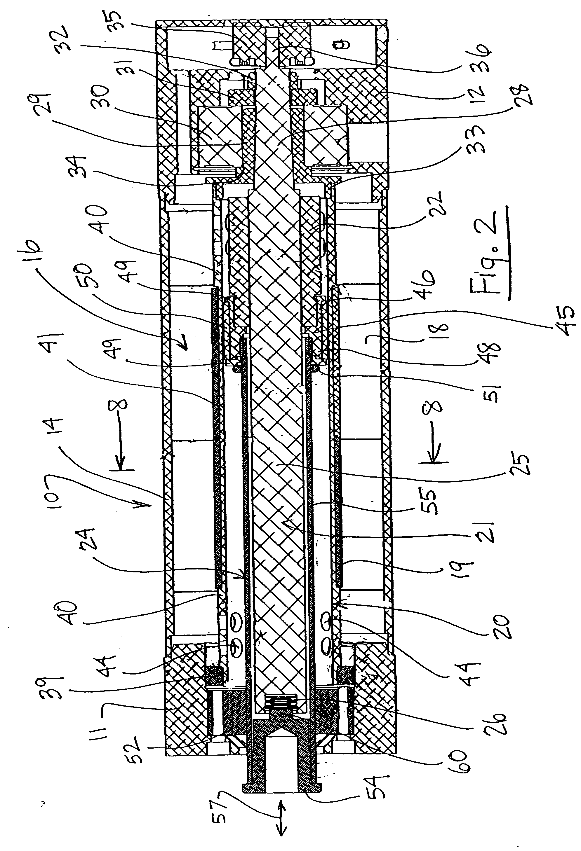
[0032] The present invention relates to an improved actuator for use in providing controlled and accurate linear movement to a work piece. Although the actuator of the present invention has applicability to a variety of work pieces and in a variety of industries, it has particular application to the actuation of welding guns, clamping fixtures, injection molding fixtures and any application in which controlled and accurate linear motion is required. One embodiment in accordance with the present invention has particular use in an application with a relatively short, but highly accurate, thrust stroke, although its use is not limited to that application.
[0033] In describing the actuator embodiments of the present invention, the terms “proximal” and “distal” will sometimes be used to define directions / orientations relative to the actuator. Specifically, the term “proximal” shall mean the direction which is toward the encoder end of the actuator, while the term “distal” shall mean the ...
PUM
| Property | Measurement | Unit |
|---|---|---|
| electrically powered | aaaaa | aaaaa |
| thrust | aaaaa | aaaaa |
| rotation | aaaaa | aaaaa |
Abstract
Description
Claims
Application Information