
Electric actuator

a technology of electric actuators and actuators, applied in the direction of belts/chains/gearings, toothed gearings, belts/chains/gearings, etc., can solve the problems of significant maintenance and other costs, inherently embodied limitations, and concern of contamination of worksites, and achieves short actuation strokes, high torque, and high precision.

Active Publication Date: 2009-10-22
TOL O MATIC
View PDF69 Cites 19 Cited by
  • Summary
  • Abstract
  • Description
  • Claims
  • Application Information

AI Technical Summary

Benefits of technology

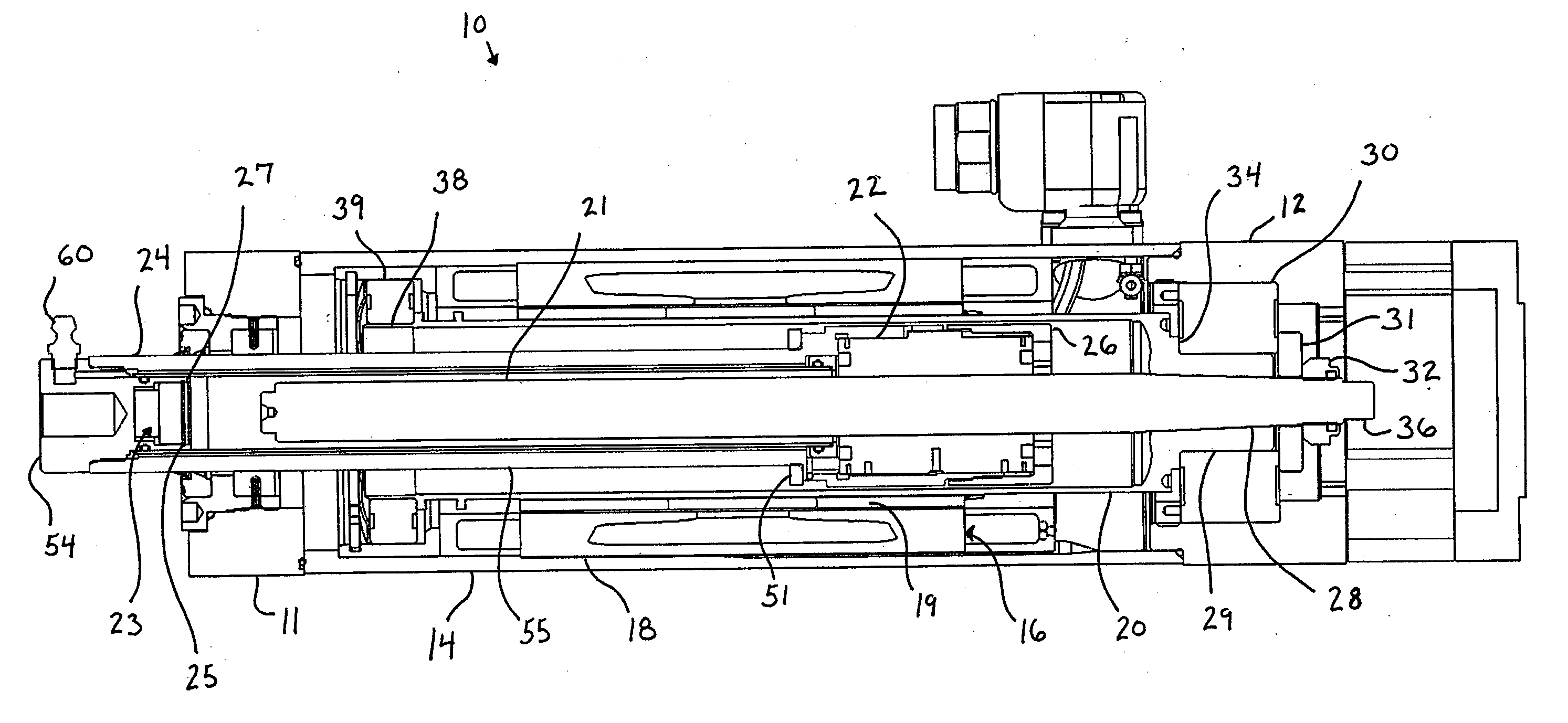
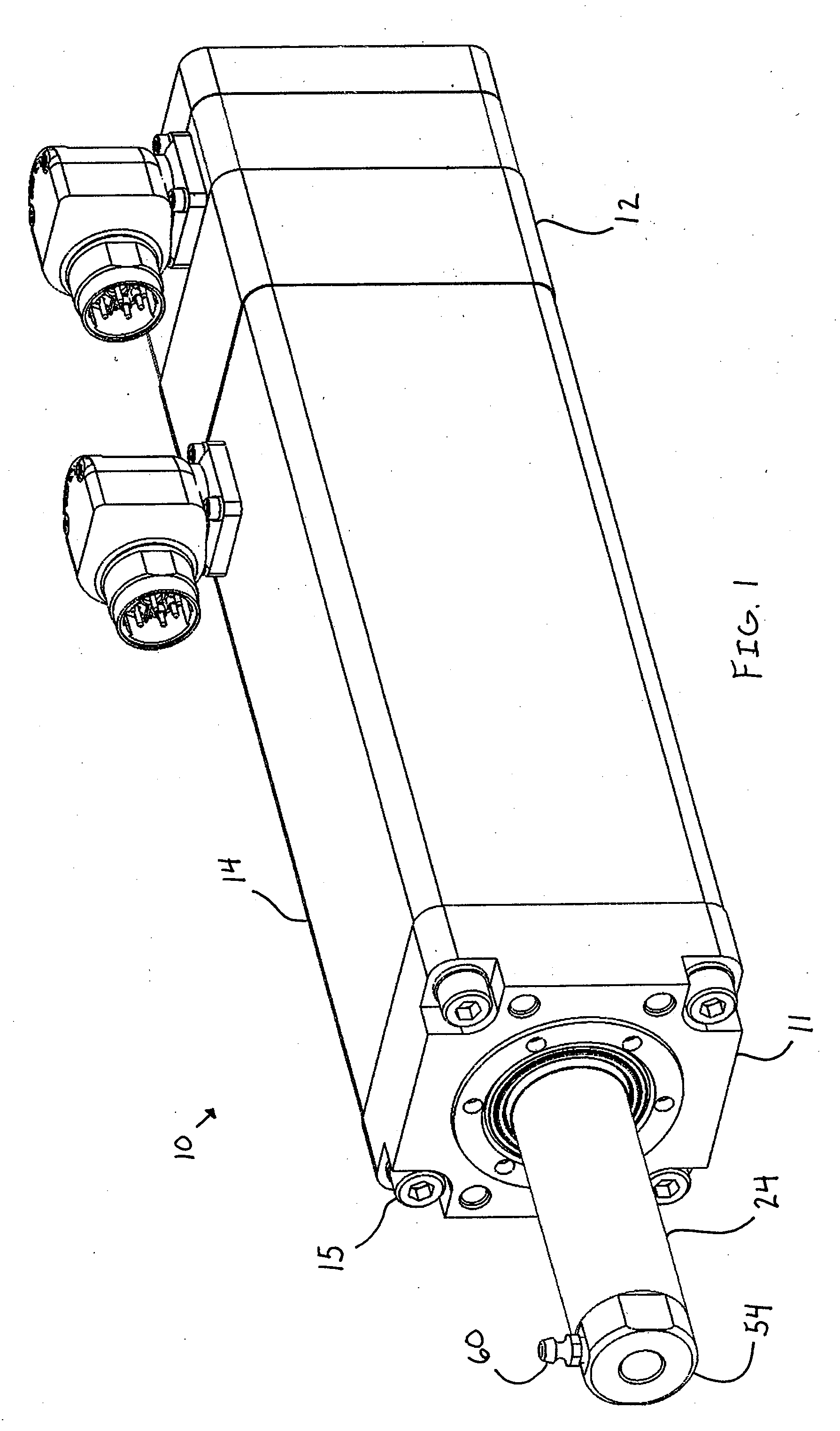
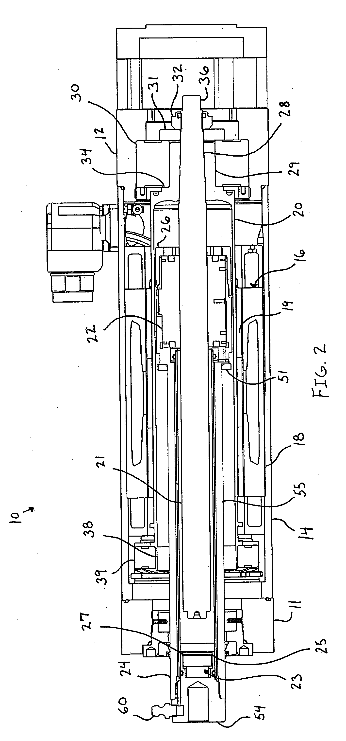
[0006]The present disclosure relates to an electric actuator with a lubricant passage having particular application to the actuation of welding guns, clamping fixtures, or the like and to injection molding and other fixtures and devices requiring relatively short actuation strokes and highly accurate positioning. More specifically, the electric actuator of one embodiment utilizes a hollow shaft motor which rotates either an externally threaded shaft or an internally threaded nut to provide controlled linear movement to a thrust or load transfer member which is in turn connected with a work piece. In one embodiment, the rotor of the hollow shaft motor is provided with an inertia reducing rotor and a unique magnet mounting arrangement which facilitates a high torque and thus high thrust actuator with minimal inertia limitations. In this embodiment, the rotor rotates the threaded shaft which results in linear movement of the threaded nut, and thus the connected thrust member. The rotor together with the thrust member and threaded shaft can be provided with improved bearing and support members to provide the thrust member with improved axial and radial stability.
[0008]Accordingly, the various embodiments of the present disclosure provide an improved actuator for welding guns, clamping fixtures, injection molding fixtures, and other fixtures and devices. Similarly, the various embodiments of the present disclosure provide means for replenishing lubrication to the force transmitting components of the actuator.

Problems solved by technology

While fluid actuators have functioned reasonably well for these purposes, they inherently embody various limitations.
One, because of the possibility of leaks and failure of seals, etc., there is always the concern of contamination of the worksite by a leaking fluid.
Second, fluid actuators necessarily require a source of pressurized fluid and thus a fluid supply system.
This leads to significant maintenance and other costs.
Third, limitations sometimes exist with respect to the accuracy and positioning of linear movement and the adjustability of such movement.
In the various prior art actuators, for example, those having an integral motor or hollow motor configuration as well as those having a conventional configuration, replenishing lubrication is very difficult, requiring the actuator to be partially or completely disassembled to access the components needing lubrication.
In some actuators, replenishing lubrication is simply not possible.

Method used


Image

  • Electric actuator
  • Electric actuator
  • Electric actuator

Examples


Embodiment Construction

[0021]The present disclosure relates to novel and advantageous actuators for use in providing controlled and accurate linear movement to a work piece. Particularly, the present disclosure relates to novel and advantageous actuators having a lubricant passage for replenishing lubrication to the force transmitting components of the actuator. Although the actuators of the present disclosure have applicability to a variety of work pieces and in a variety of industries, they may have particular application to the actuation of welding guns, clamping fixtures, injection molding fixtures and any application in which controlled and accurate linear motion is required. One embodiment in accordance with the present invention has particular use in an application with a relatively short, but highly accurate, thrust stroke, although its use is not limited to that application.

[0022]In describing the actuator embodiments of the present disclosure, the terms “proximal” and “distal” will sometimes be ...


PUM


Abstract

An electrically powered linear actuator having a thrust assembly, a motor with a hollow rotor surrounding at least a portion of the thrust assembly, and a lubricant passage for replenishing lubricant to the force transmitting components of the actuator.

Description

CROSS-REFERENCE TO RELATED APPLICATION(S) [0001]This application claims priority to U.S. provisional patent application Ser. No. 61 / 046,243, filed Apr. 18, 2008, which is incorporated herein by reference in its entirety.FIELD OF THE INVENTION [0002]The present disclosure relates generally to an electrically powered linear actuator and more particularly to an electrically powered actuator having a lubricant passage and adapted for a variety of robotic or other applications. The actuator of the present disclosure has particular application to the control of robotic, pedestal, or fixture welding guns and specifically, welding guns such as those utilized in various industries such as the automotive industry, to the injection molding field or other applications requiring a short stroke, to the actuation of clamping fixtures and the like in various industries such as the automotive industry, and to the linear movement of various apparatus requiring highly accurate positioning, among other...

Claims


Application Information

Patent Timeline
IPC IPC(8): F16H25/20
CPCF16H57/0497Y10T74/18656Y10T74/18576Y10T74/18744F16H25/20F16H2025/2075
Inventor HOLKER, BRETT C.KARLS, JEFFFORBORD, JEREMY R.
Owner TOL O MATIC
Learn More