Method for manufacturing a linear actuator

a manufacturing method and actuator technology, applied in the direction of manufacturing tools, mechanical equipment, manufacturing tools, etc., can solve the problems of complex manufacturing of actuators, inability to meet the needs of customers, etc., to achieve short actuation strokes and high accuracy of positioning

Active Publication Date: 2014-09-02
TOL O MATIC
View PDF9 Cites 5 Cited by
  • Summary
  • Abstract
  • Description
  • Claims
  • Application Information

AI Technical Summary

Benefits of technology

[0006]The present disclosure relates to an improved method for manufacturing a linear actuator. In some embodiments, the manufactured device can be used to replace pneumatic cylinders, and allows for control of linear position and acceleration of a thrust member. The present disclosure particularly relates to the manufacture of linear actuators used in conjunction with injection molding devices and the like, and other fixtures and devices requiring relatively short actuation strokes and highly accurate positioning.

Problems solved by technology

However, the manufacture of these devices can often be complicated and not always cost-effective.
The process requires a significant amount of time and exactness to form a well-working actuator.
The difficulty of the process is further intensified when the parts being worked on, such as the nut, are relatively small.

Method used


Image

  • Method for manufacturing a linear actuator
  • Method for manufacturing a linear actuator
  • Method for manufacturing a linear actuator

Examples


Embodiment Construction

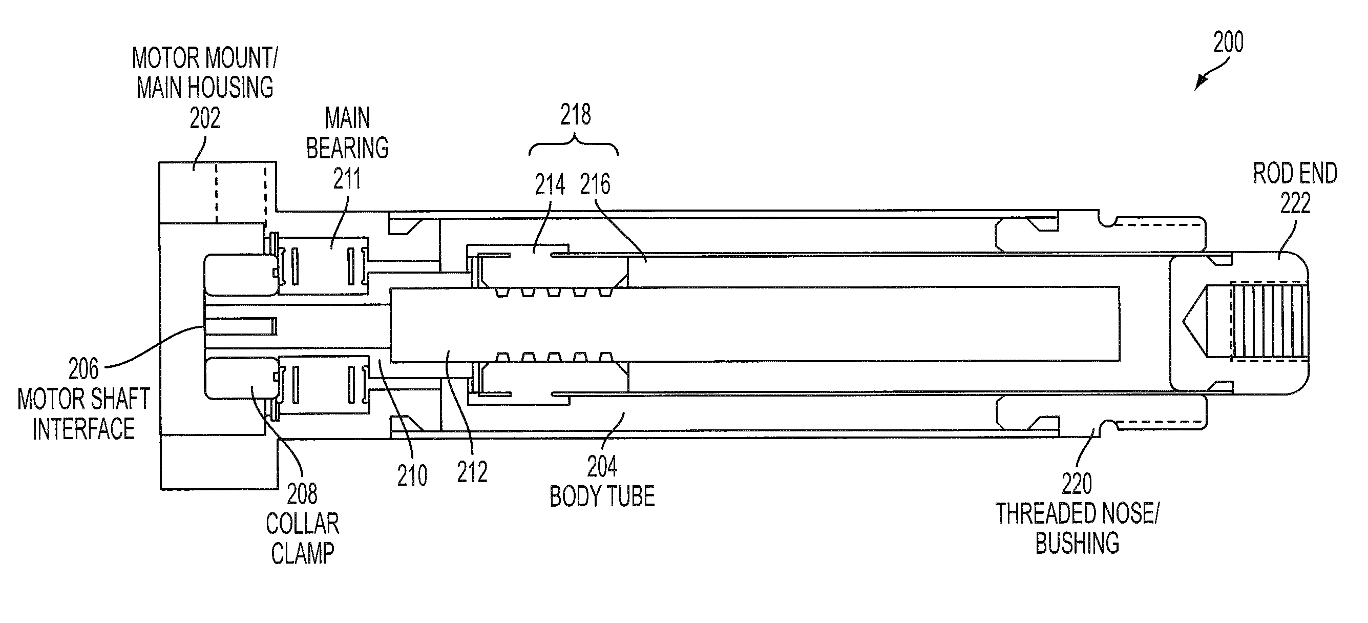
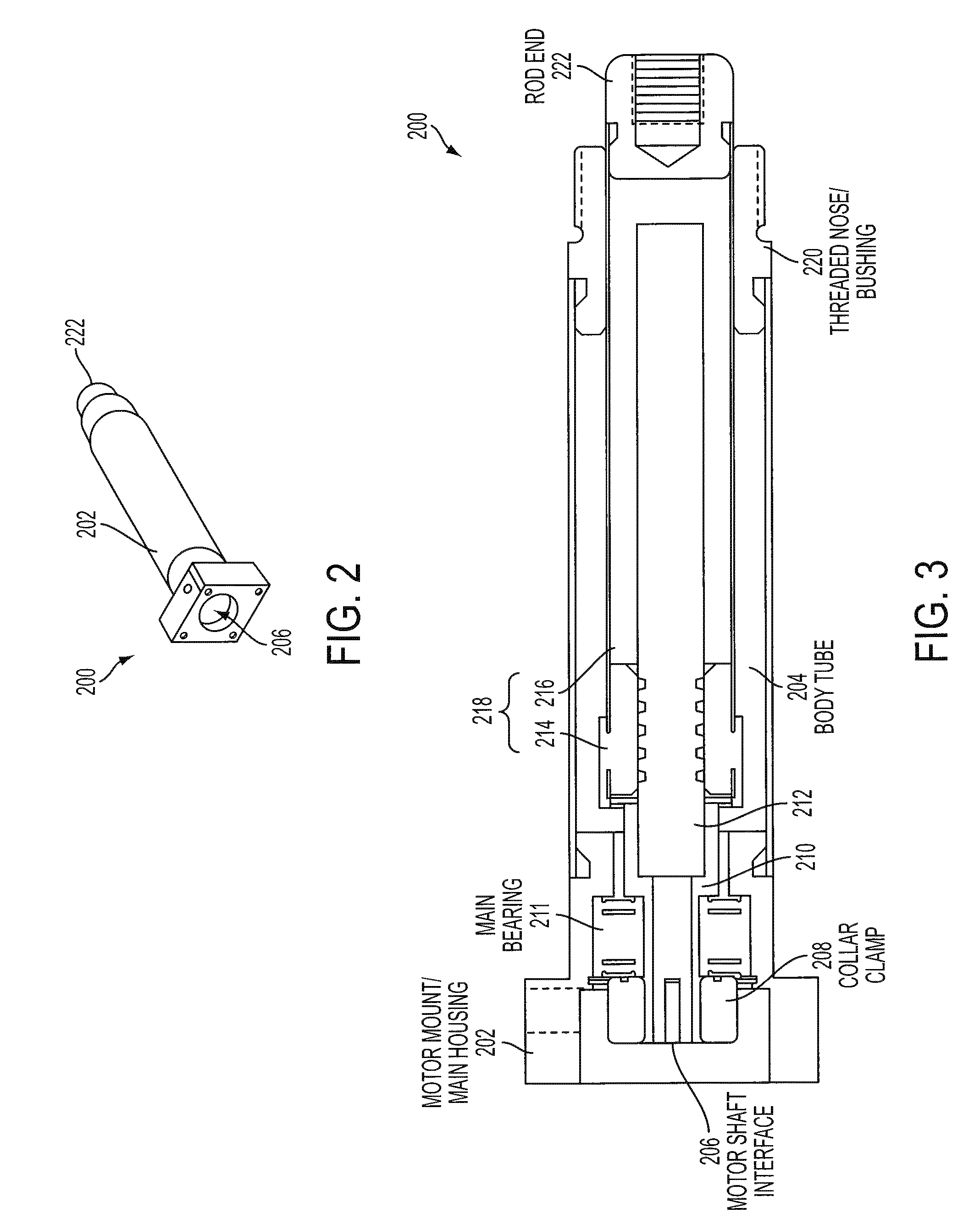
[0017]The present disclosure relates to a screw-driven linear actuator, and an improved method of manufacture. Particularly, the present disclosure relates to novel and advantageous methods for overmolding a plastic nut and thrust tube assembly. Additionally, the present disclosure relates to novel and advantageous methods for attaching the screw shaft to the bearing journal assembly. These methods can simplify the construction, save time, and reduce the costs during manufacture of the actuator.

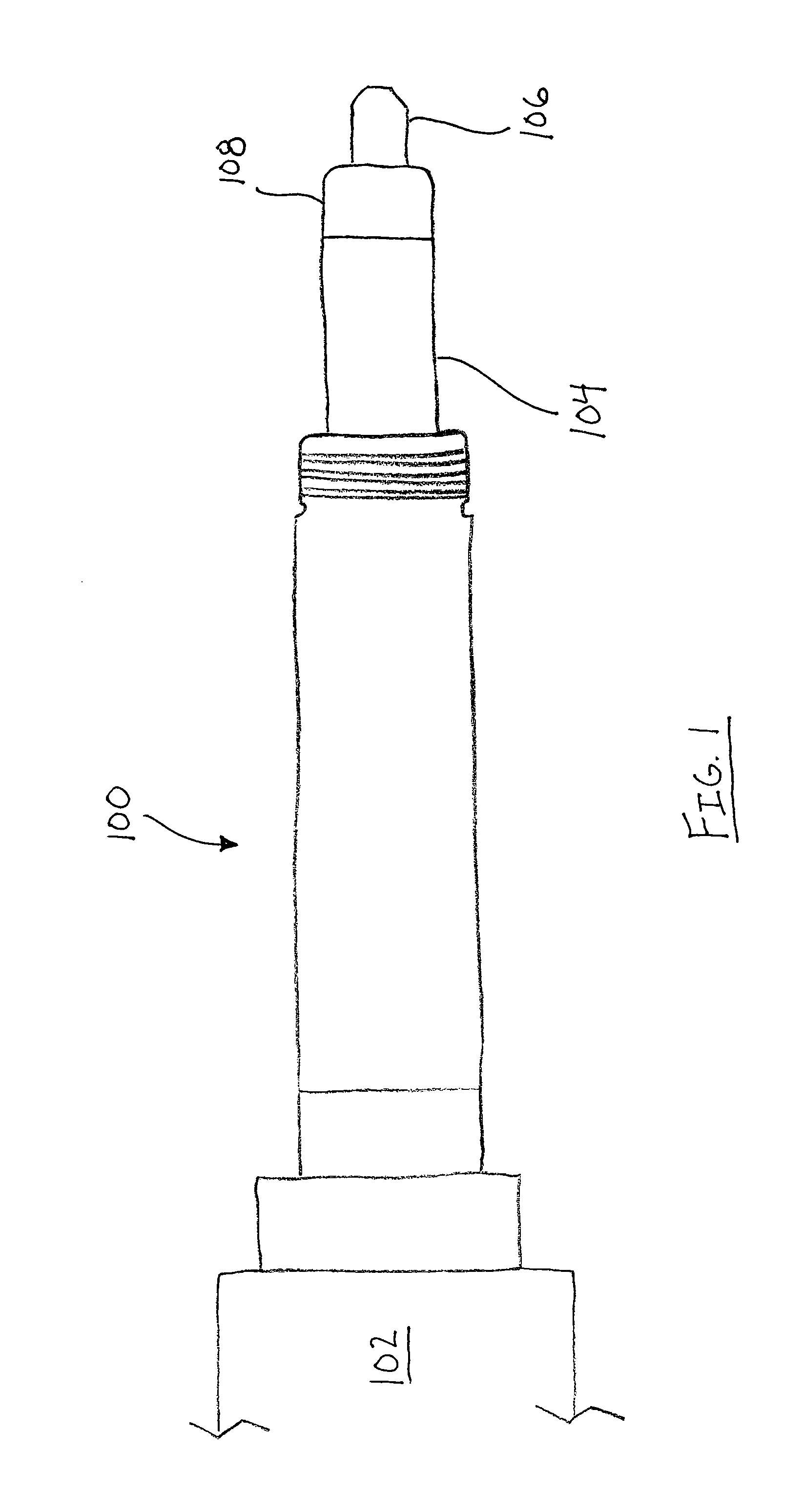
[0018]FIG. 1 illustrates a system including a screw-driven linear actuator 100 according to the present disclosure. As can be seen in FIG. 1, a motor 102 may be attached to the linear actuator 100 providing the driving power to the screw shaft inside the actuator. The actuator 100 transfers the rotary motion of the motor to linear motion through interaction of the screw shaft and a thrust tube assembly 104. A workpiece or tool 106 may be attached to a workpiece connection end 108 of the thrus...


PUM

PropertyMeasurementUnit
circumferenceaaaaaaaaaa
sizesaaaaaaaaaa
thread widthsaaaaaaaaaa

Abstract

A method for manufacturing a linear actuator includes inserting a portion of a thrust member of the actuator into a casting portion of a molding apparatus. The casting portion includes a model screw member having a threaded portion. A molding material can be added into the cast portion to overmold a nut to the thrust member. Thus, the nut will include a threaded portion on an internal circumference mateable with the threaded portion of the model screw member. The overmolded nut and thrust tube member may be coupled to a screw shaft of the actuator, such that the threaded portion of the nut mates with a threaded portion of the screw shaft.

Description

CROSS REFERENCE TO RELATED APPLICATION(S)[0001]This application claims priority to U.S. Provisional Patent Application No. 61 / 308,726, filed on Feb. 26, 2010, the entire contents of all of which are hereby incorporated herein by reference in their entirety.FIELD OF THE INVENTION[0002]The present disclosure relates generally to an electrically powered linear screw-driven actuator. More particularly, the present disclosure relates to a method of manufacturing an overmolded plastic nut and thrust tube assembly, and a bearing journal assembly for a linear actuator. The present disclosure has particular application to the applications requiring a short stroke, the actuation of injection molding and clamping fixtures and the like, and the linear movement of various apparatuses requiring highly accurate positioning, among others.BACKGROUND OF THE INVENTION[0003]Several industries have utilized linear actuators to control the movements of automated fixtures. This requires controlled linear ...

Claims


Application Information

Patent Timeline
Patent Type & Authority Patents(United States)
IPC IPC(8): B21D53/10F16H25/20F16H25/24
CPCF16H25/20F16H2025/2481Y10T29/49984Y10T29/49988Y10T29/49982Y10T74/18576Y10T29/49705Y10T29/4998Y10T29/49908
Inventor ROSENGREN, GARY W.GRUNERUD, WYATT A.KARLS, JEFF
Owner TOL O MATIC
Why Eureka
Try Eureka