Image forming method and apparatus

a technology of image forming and forming method, applied in the direction of printing, other printing apparatus, etc., can solve the problems of serious deterioration in image quality, poor efficiency, and unintended stripe defect (stripe non-uniformity or “banding”), and achieve the effect of reducing the perceptibility of dot faults and low perceptibility

Inactive Publication Date: 2005-11-17
FUJIFILM CORP
View PDF5 Cites 26 Cited by
  • Summary
  • Abstract
  • Description
  • Claims
  • Application Information

AI Technical Summary

Benefits of technology

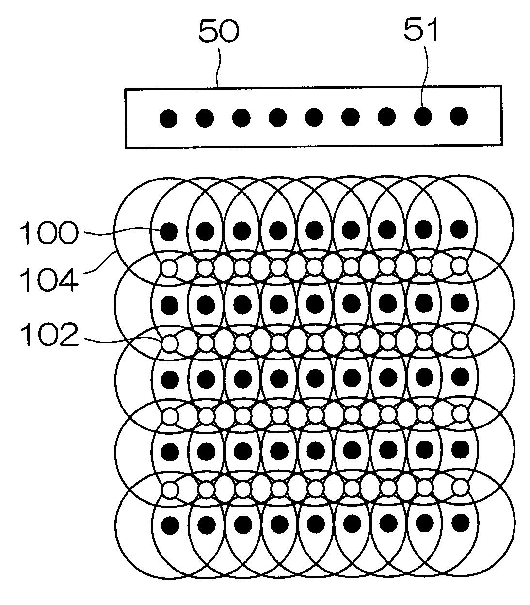
[0033] According to the present invention, a pattern for a dot arrangement according to which stripe-shaped non-uniformity (banding) is of low perceptibility is selected on the basis of a droplet deposition rate calculated from the image data that is to be printed, and a dot line is ...

Problems solved by technology

If a particular nozzle of the nozzle group suffers an ejection failure, then dots that should originally have been formed on the recording medium by that nozzle are missing, and an unintended stripe-shaped defect (stripe non-uniformity or “banding”) is thereby produced in the image formed on the recording medium.
In particular, in the case of a device configuration that completes printing by means of a single sub-scanning operation, using a line-type recording head in which a plurality of nozzles are arranged, u...

Method used


Image

  • Image forming method and apparatus
  • Image forming method and apparatus
  • Image forming method and apparatus

Examples


Embodiment Construction

General Configuration of Inkjet Recording Apparatus

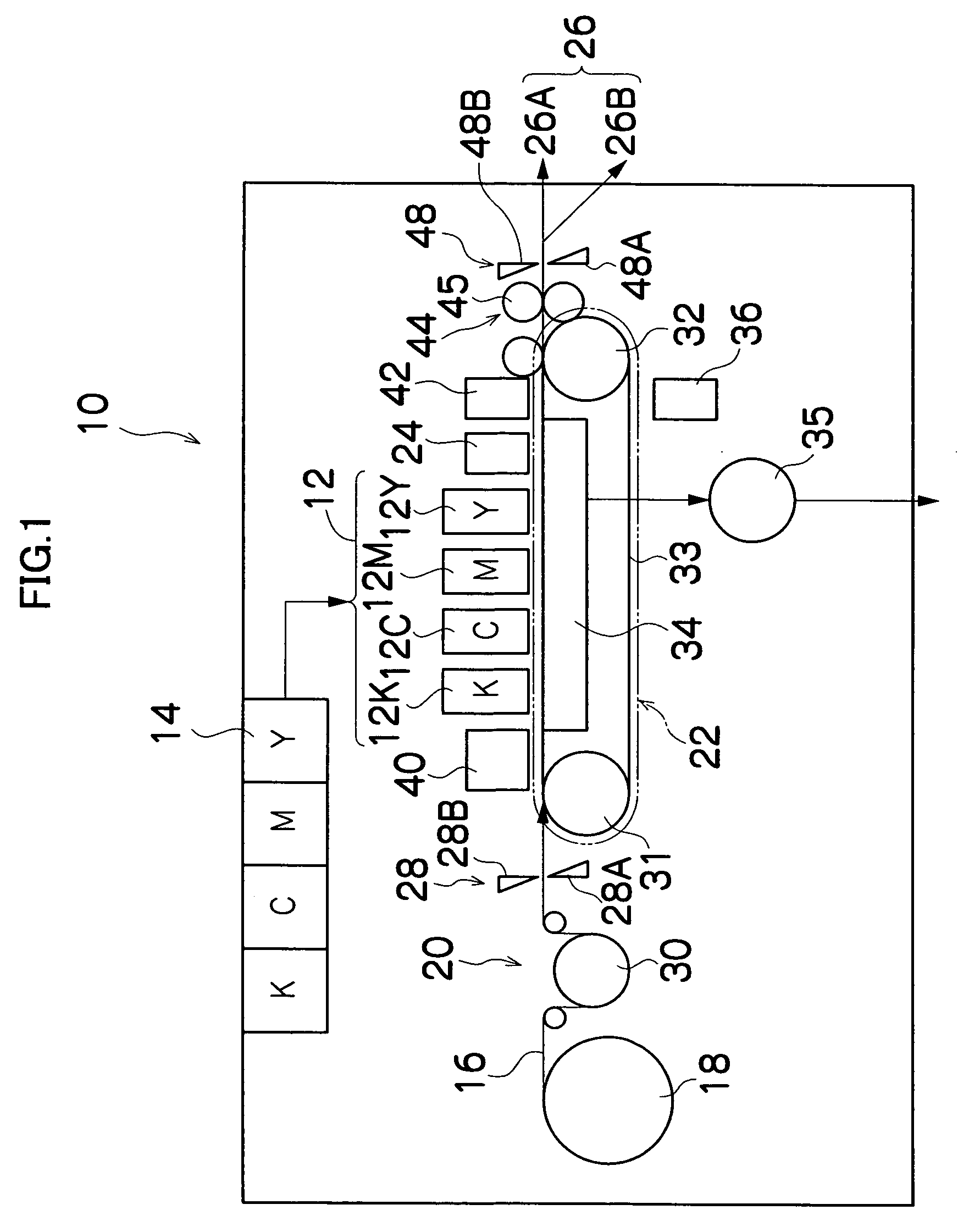
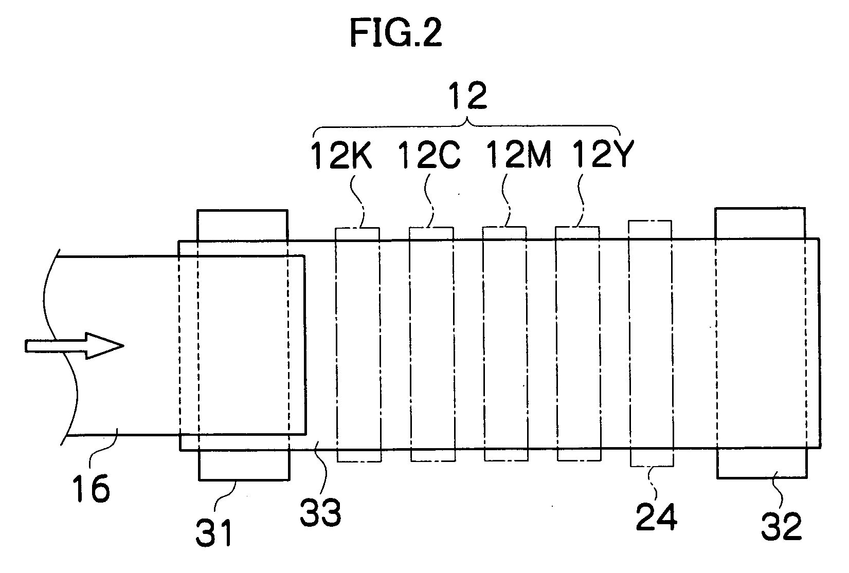
[0051]FIG. 1 is a general configuration diagram of an inkjet recording apparatus including an image forming apparatus according to an embodiment of the present invention. As shown in FIG. 1, the inkjet recording apparatus 10 comprises: a printing unit 12 having a plurality of inkjet heads (hereafter, called “heads”) 12K, 12C, 12M, and 12Y provided for ink colors of black (K), cyan (C), magenta (M), and yellow (Y), respectively; an ink storing and loading unit 14 for storing inks of K, C, M and Y to be supplied to the print heads 12K, 12C, 12M, and 12Y; a paper supply unit 18 for supplying recording paper 16 which is a recording medium; a decurling unit 20 removing curl in the recording paper 16; a suction belt conveyance unit 22 disposed facing the nozzle face (ink-droplet ejection face) of the printing unit 12, for conveying the recording paper 16 while keeping the recording paper 16 flat; a print determination unit 24 for readin...


PUM


Abstract

The image forming method for forming an image on a recording medium by forming dots on the recording medium by depositing droplets on the recording medium by a recording head having a plurality of nozzles ejecting the droplets while moving the recording head and the recording medium relatively to each other by conveying at least one of the recording head and the recording medium in a relative conveyance direction, wherein the image to be formed is divided into a plurality of regions; a density in each of the plurality of regions is set as a prescribed density so as to form the image; a droplet deposition rate is defined as a ratio of a number of the dots actually formed by depositing the droplets from one of the nozzles within each of the plurality of regions with respect to a maximum number of the dots formable by depositing the droplets from the one of the nozzles within the region; and tonal gradation in the image is represented by means of a collection of the dots based on a dot arrangement specified according to the droplet deposition rate calculated from image data of the image to be formed, the image forming method comprises: a droplet deposition rate calculation step of calculating the droplet deposition rate from the image data; a dot arrangement specification step of specifying a dot arrangement pattern from the droplet deposition rate calculated in the droplet deposition rate calculation step; and a droplet deposition control step of controlling droplet deposition operation performed by the recording head in such a manner that the dot arrangement pattern specified in the dot arrangement specification step is achieved, wherein, in at least one of the plurality of the regions where the droplet deposition rate calculated in the droplet deposition rate calculation step is lower than a maximum droplet deposition rate and is higher than a prescribed reference value, a dot line in a main scanning direction substantially perpendicular to the relative conveyance direction is formed in which the dots are continuously aligned so as to mutually overlap by a prescribed overlap ratio, in accordance with the droplet deposition rate calculated in the droplet deposition rate calculation step.

Description

BACKGROUND OF THE INVENTION [0001] 1. Field of the Invention [0002] The present invention relates to an image forming method and apparatus, and more particularly, to droplet deposition control technology suitable for reducing deterioration of image quality caused by ejection failure of a droplet ejection port (nozzle) of an inkjet recording apparatus or other image forming apparatus comprising an ejection head having a nozzle row in which a plurality of nozzles are arranged through a length corresponding to the entire width of a recording medium. [0003] 2. Description of the Related Art [0004] In an inkjet printer, for a variety of reasons, a situation may occur in which it becomes impossible to eject ink from a nozzle. If a particular nozzle of the nozzle group suffers an ejection failure, then dots that should originally have been formed on the recording medium by that nozzle are missing, and an unintended stripe-shaped defect (stripe non-uniformity or “banding”) is thereby produc...

Claims


Application Information

Patent Timeline
IPC IPC(8): B41J2/205B41J2/21B41J2/01B41J29/38
CPCB41J2/2132
Inventor YAMANOBE, JUN
Owner FUJIFILM CORP
Why Eureka
Try Eureka