
Ink ejection method, ink ejection apparatus, and image forming apparatus comprising same

a technology of ink ejection and ink ejection, which is applied in the direction of printing, other printing apparatus, etc., can solve the problems of inability to achieve uniform stripe shape, etc., to achieve low moiré effect, reduce moiré effect, and suppress banding occurrence

Inactive Publication Date: 2006-03-09
FUJIFILM CORP
View PDF8 Cites 5 Cited by
  • Summary
  • Abstract
  • Description
  • Claims
  • Application Information

AI Technical Summary

Benefits of technology

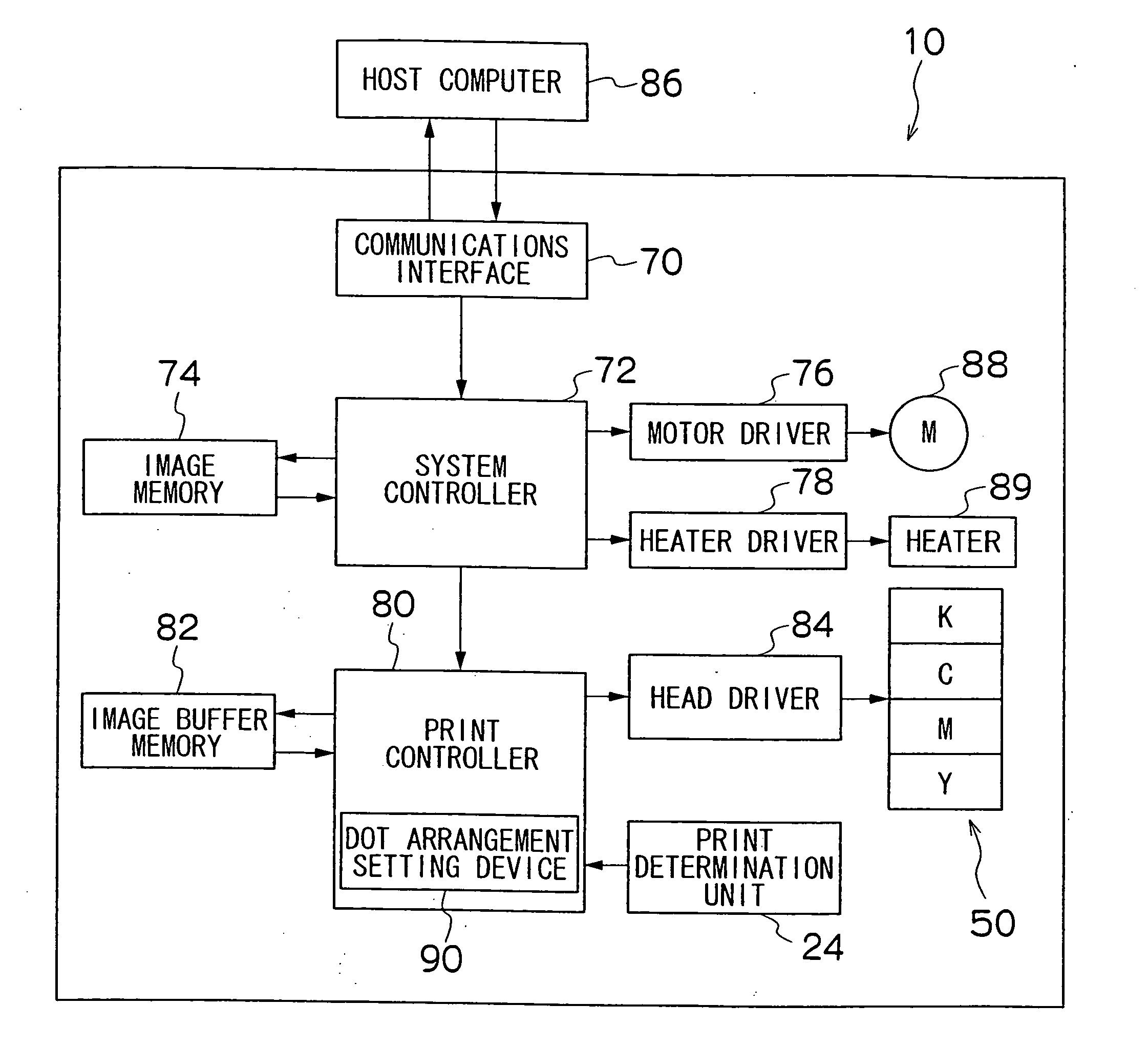
[0030] The present invention is contrived in view of such circumstances, and an object thereof is to provide an ink ejection method, an ink ejection apparatus, and an image forming apparatus comprising same which can reduce moiré effects during recording color image, while keeping the perceptibility of banding low.

Problems solved by technology

Furthermore, since the number of inks used is limited, various methods have been used in the prior art in order to form a tonally graduated image with those limited inks.
In a conventional inkjet recording apparatus, there is a problem in that “banding” (stripe-shaped non-uniformity) is liable to occur, due to errors in the paper feed operation, variations in the nozzles, or the like.
However, a full-line head which covers the entire width of the paper so as to be able to record an image over the entire surface of the recording paper by performing one operation of conveying the recording paper and the print head relatively to each other (namely, a single-pass operation), is liable to cause the banding in the paper conveyance direction due to variations between nozzles.
Therefore, since it is not possible to perform shingling as described above, there is a necessity to resolve the problem of banding in the paper conveyance direction.
In the single-pass full-line head such as described above, consideration is given to banding in the paper conveyance direction, which is a serious problem in this type of head.
In this case, since the banding S1 in the paper conveyance direction is clearly visible, it is found that a dot arrangement by the Bayer dithering method is liable to cause the banding in the paper conveyance direction.
In this case, since the banding S2 in the paper conveyance direction is also clearly visible, it is found that a dot arrangement based on halftone dot dithering is liable to cause the banding in the paper conveyance direction.
In this case, since the striping S3 in the paper conveyance direction is also clearly discernable, it is found that a stripe pattern at a 0-degree angle is liable to cause the striping in the paper conveyance direction.
Furthermore, an isotropic pattern which does not have a uniform basic arrangement lies between the two types of pattern described above.
However, if using a regular dot arrangement such as a striped arrangement, there is a problem that moiré effects occur when a color image is formed by ejecting inks of respective colors from heads of respective colors.
More specifically, if the directions of stripes of the respective colors, such as cyan (C), magenta (M), yellow (Y), and black (K) (namely, the angle of the stripes from the paper conveyance direction) are set to the same direction, then interference between the respective colors may occur due to the occurrence of slight angular displacement caused by the inclination of the heads, or the like.
Therefore, as that shown in FIG. 16, since a low-frequency striping (a moiré pattern) occurs, there is a marked problem in terms of image quality.
However, in Japanese Patent Application Publication Nos. 2004-15674 and 2004-80065, since the image forming apparatus has a composition in which errors occurring in the main scanning direction and sub-scanning direction caused by shuttle scanning are absorbed equally, there is a problem that the banding in the paper conveyance direction can not be resolved by a single-pass type full-line head such as described above.

Method used


Image

  • Ink ejection method, ink ejection apparatus, and image forming apparatus comprising same
  • Ink ejection method, ink ejection apparatus, and image forming apparatus comprising same
  • Ink ejection method, ink ejection apparatus, and image forming apparatus comprising same

Examples


Embodiment Construction

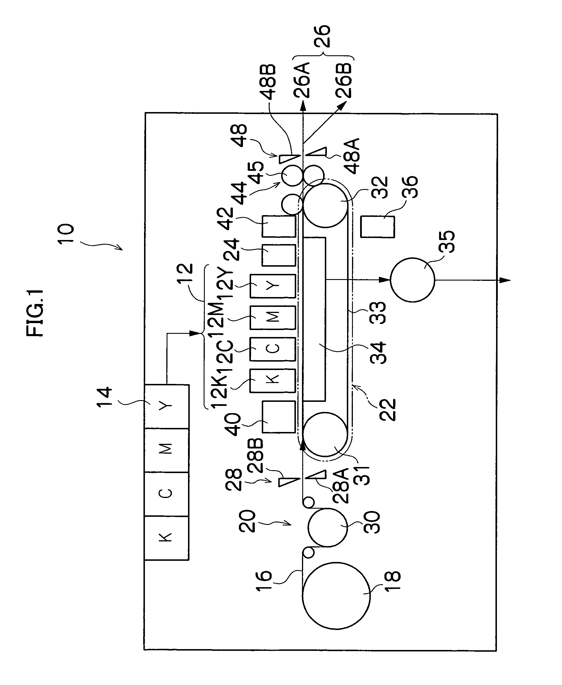
[0073]FIG. 1 is a general schematic drawing of an inkjet recording apparatus as an image forming apparatus according to an embodiment of the present invention.

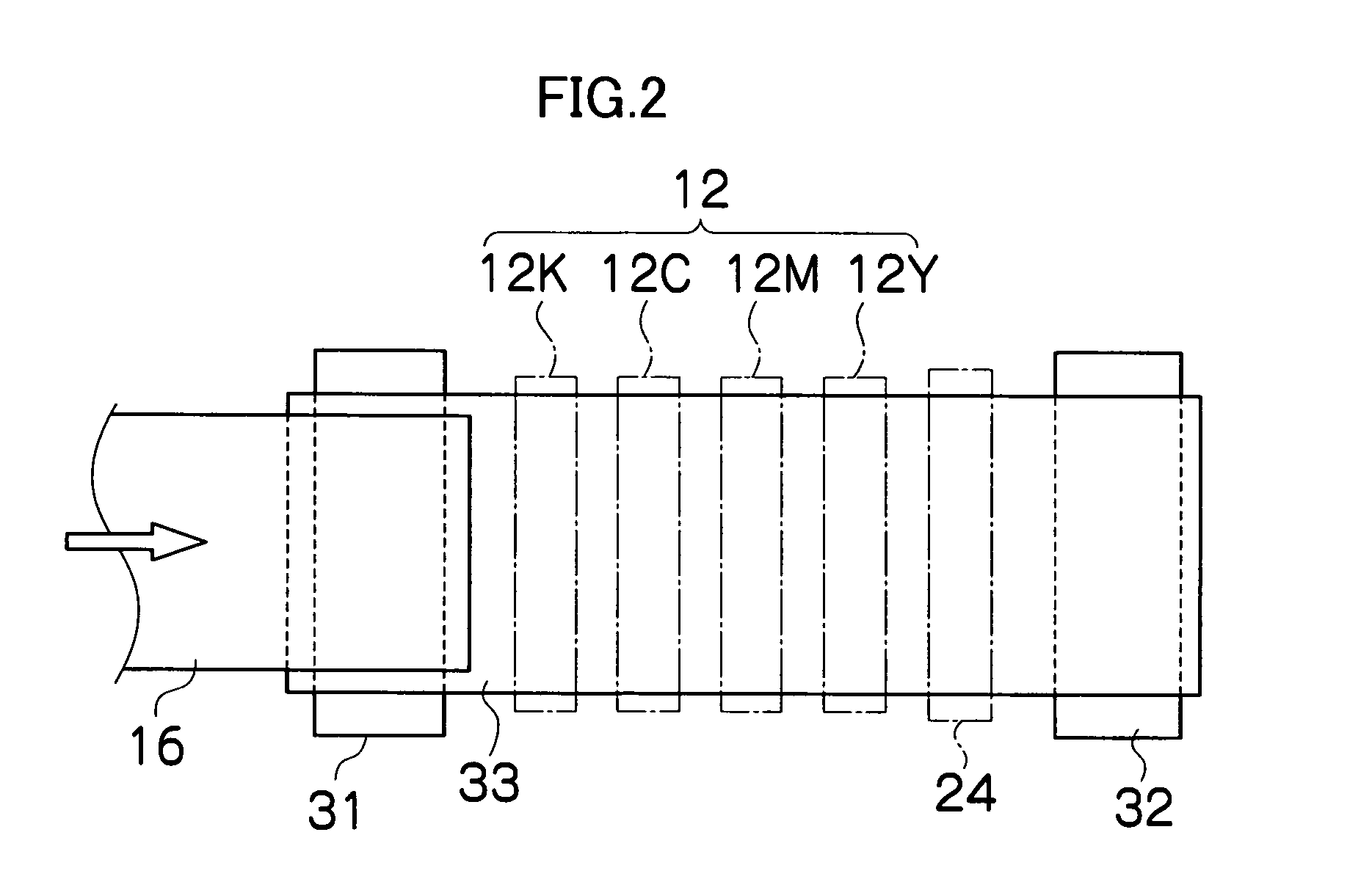
[0074] As shown in FIG. 1, the inkjet recording apparatus 10 comprises: a printing unit 12 having a plurality of print heads (liquid ejection heads) 12K, 12C, 12M, and 12Y for ink colors of black (K), cyan (C), magenta (M), and yellow (Y), respectively; an ink storing and loading unit 14 for storing inks of K, C, M and Y to be supplied to the print heads 12K, 12C, 12M, and 12Y; a paper supply unit 18 for supplying recording paper 16; a decurling unit 20 for removing curl in the recording paper 16 supplied from the paper supply unit 18; a belt conveyance unit 22 disposed facing the nozzle face (ink-droplet ejection face) of the printing unit 12, for conveying the recording paper 16 while keeping the recording paper 16 flat; a print determination unit 24 for reading the printed result produced by the printing unit 12; and a pap...


PUM


Abstract

The ink ejection apparatus comprises: a plurality of ink ejection heads which are provided corresponding to a plurality of colors to record a color image onto a recording medium by performing one relative movement with respect to the recording medium, the ink ejection heads having a plurality of nozzles for ejecting respective inks of the colors toward the recording medium; and a dot arrangement setting device which sets each of dot arrangements of the inks of the respective colors on the recording medium according to a prescribed stripe pattern, wherein among absolute values of stripe angles formed by the inks of the colors with respect to a direction of the relative movement of the recording medium, the absolute value of the stripe angle formed by the ink of yellow is set to be a minimum.

Description

BACKGROUND OF THE INVENTION [0001] 1. Field of the Invention [0002] The present invention relates to an ink ejection method, an ink ejection apparatus, and an image forming apparatus comprising same, and more particularly to an image forming technology which uses a stripe pattern for the arrangement of dots formed by ejected inks of respective colors. [0003] 2. Description of the Related Art [0004] Conventionally, as an image forming apparatus, an inkjet recording apparatus (inkjet printer) is known, which comprises an ink ejection apparatus (liquid ejection apparatus) including an inkjet head (ink ejection head) having an arrangement of a plurality of nozzles (liquid ejection ports) and which records images on a recording medium by ejecting ink from the nozzles toward the recording medium while causing the inkjet head and the recording medium to move relatively to each other. [0005] In an inkjet recording apparatus of this kind, an image is created by means of a plurality of dots f...

Claims


Application Information

Patent Timeline
Patent Type & Authority Applications(United States)
IPC IPC(8): B41J29/38
CPCB41J2/2132
Inventor CHIWATA, YUHEI
Owner FUJIFILM CORP
Learn More