
Method and device for measuring cavitation

a cavitation and measurement method technology, applied in the direction of material transmission, fluid analysis using sonic/ultrasonic/infrasonic waves, etc., can solve the problem of no means in real time for measuring cavitation uniformity or density in the vicinity of specific sites on the wafer, pitting and damage, etc. problem, to achieve the effect of accurate estimation of the total number, short in

Inactive Publication Date: 2005-11-17
LAM RES AG
View PDF3 Cites 10 Cited by
  • Summary
  • Abstract
  • Description
  • Claims
  • Application Information

AI Technical Summary

Benefits of technology

"The invention provides a system for measuring cavitation in a fluid by creating a dark chamber and using a photomultiplier module to detect and convert photons produced by cavitation. The system can estimate the location and number of cavitation events within a selected volume of the fluid. The invention also includes a probe for detecting the presence of cavitation in a fluid by creating a thin plate between two fluids and using a photomultiplier to detect the energy perturbation associated with cavitation. The technical effects of the invention include improved accuracy in measuring cavitation and the ability to map the distribution of cavitation events within a fluid."

Problems solved by technology

One problem is discrimination of the energy pulses produced by the perturbation of interest from energy pulses introduced by other agencies that are not of interest.
However, in many cavitation systems cavitation occurs non-uniformly, often at certain specific sites on the wafer, leading to pitting and damage.
There is currently no means for measuring cavitation uniformity or density in the vicinity of specific sites on the wafer in real time.

Method used


Image

  • Method and device for measuring cavitation
  • Method and device for measuring cavitation
  • Method and device for measuring cavitation

Examples


Embodiment Construction

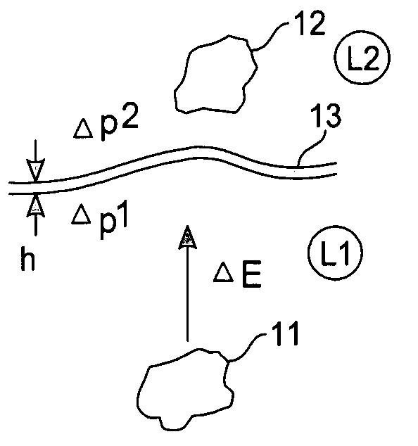
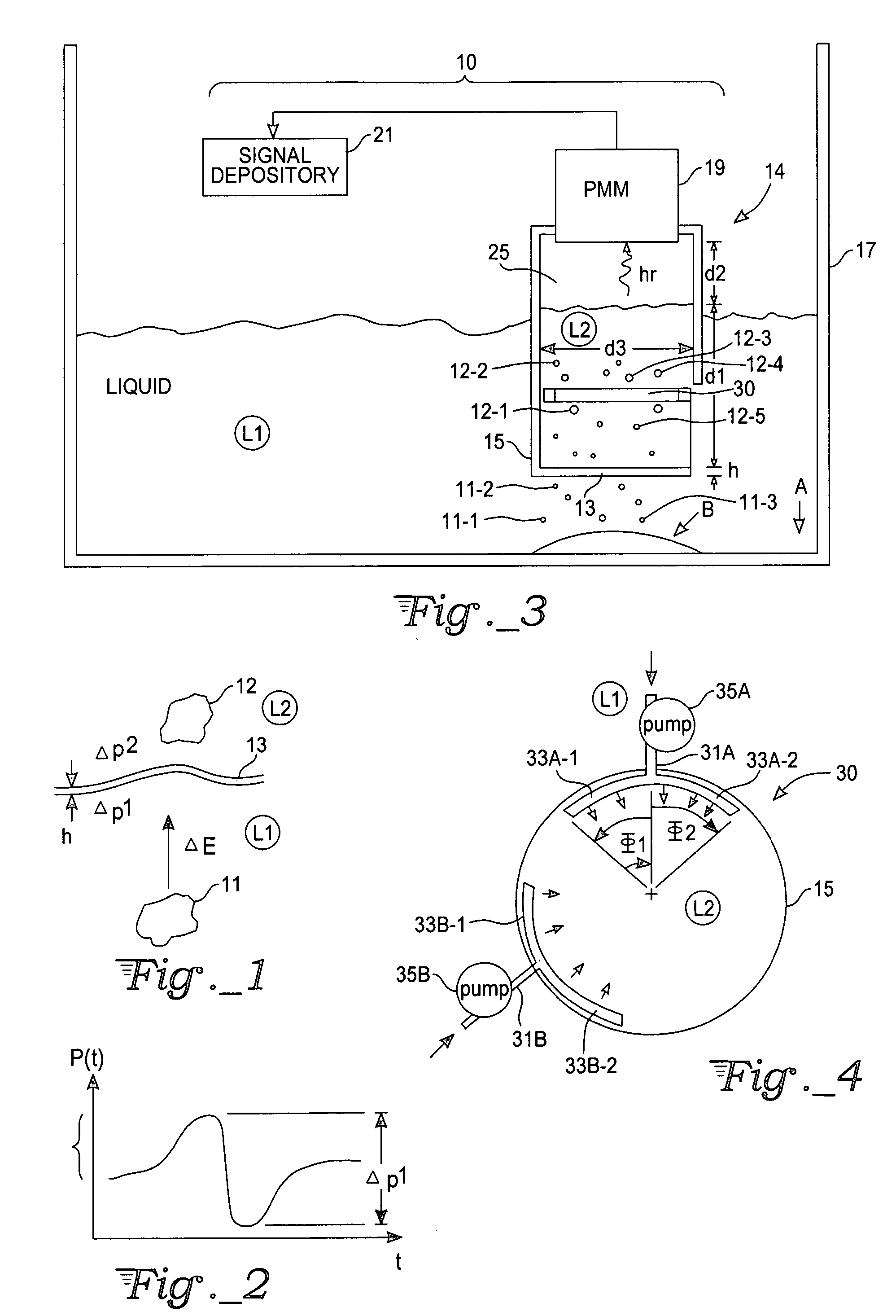
[0018] A cavitation event, illustrated in FIG. 1, involves an implosion of a gas filled or empty void 11 that is surrounded by a liquid L. The implosion produces a pulse of sonic and / or light energy ΔE that moves off in some direction. The energy pulse may have a corresponding temporary local temperature rise ΔT as high as 5500° K., or even higher, and may produce a temporary local pressure rise Δpl(+) as large as 50-150 atmospheres, or even higher, followed by a somewhat larger temporary pressure reduction Δp 1(−), as illustrated graphically in FIG. 2. If the cavitation void or associated energy pulse 11 occurs adjacent to, and is received by, a very thin plate 13, shown in FIG. 1, with a plate thickness h of the order of a fraction of a millimeter (h˜0.025-0.25 mm, preferably no more than 0.125 mm) or less, the plate will temporarily deform in response to receipt of the corresponding energy perturbation (with corresponding pressure increment Δp 1, as illustrated in FIG. 2) and wil...


PUM

PropertyMeasurementUnit
thicknessaaaaaaaaaa
thicknessaaaaaaaaaa
thicknessaaaaaaaaaa

Abstract

A method, probe, and system for detecting presence of cavitation in a fluid and measuring cavitation density and intensity of a specific locale in the fluid. A first cavitation void and associated energy perturbation, produced in a first fluid, moves within the first fluid and is received at a very thin plate, which separates the first fluid from a second fluid and is part of a light-proof chamber containing the second fluid. An energy perturbation in the first fluid is received at the thin plate and produces at least one cavitation void or associated energy perturbation in the second fluid; and the energy perturbation in the second fluid is eventually converted into an electromagnetic signal. This signal is received by a photomultiplier and converted to an electronic signal that indicates the presence of cavitation. The system can distinguish between cavitation voids produced at one location and / or time interval and voids produced at another location and / or another time interval.

Description

CROSS-REFERENCE TO RELATED APPLICATION [0001] This is a continuation of pending U.S. patent application Ser. No. 09 / 614,485 filed Jul. 10, 2000.FIELD OF THE INVENTION [0002] This invention relates to testing for the presence of, and the frequency of occurrence of, cavitation in a fluid. The present invention provides measurement of the cavitation density and / or intensity of a selected volume in a fluid. BACKGROUND OF THE INVENTION [0003] Cavitation in a liquid, with a corresponding release of sound energy and / or light energy, is a common occurrence where a perturbing force is present in the liquid. This force can arise from a locally random perturbation, such as a stirring motion or similar action introduced at selected portions (less than all) of the liquid; or the force can arise from perturbations that are coherent over short distances, such as a liquid perturbation intentionally introduced by a transducer immersed in the liquid. One problem is discrimination of the energy pulses...

Claims


Application Information

Patent Timeline
Patent Type & Authority Applications(United States)
IPC IPC(8): G01N29/02G01N29/032H04B17/00
CPCG01N21/1702G01N21/70H01L21/67028G01N2021/8411G01N2201/0833G01N21/8507
Inventor FERRELL, GARY W.
Owner LAM RES AG
Learn More