

Channel impulse response estimating decision feedback equalizer
- Summary
- Abstract
- Description
- Claims
- Application Information
AI Technical Summary
Benefits of technology
Problems solved by technology
Method used
Image

Examples
Embodiment Construction
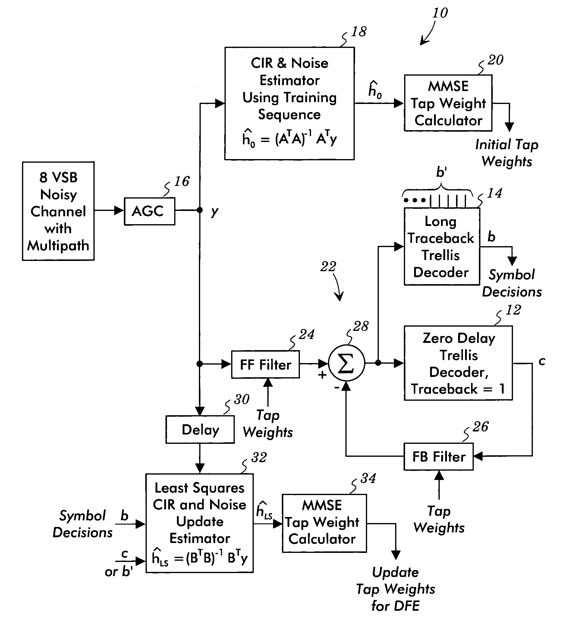
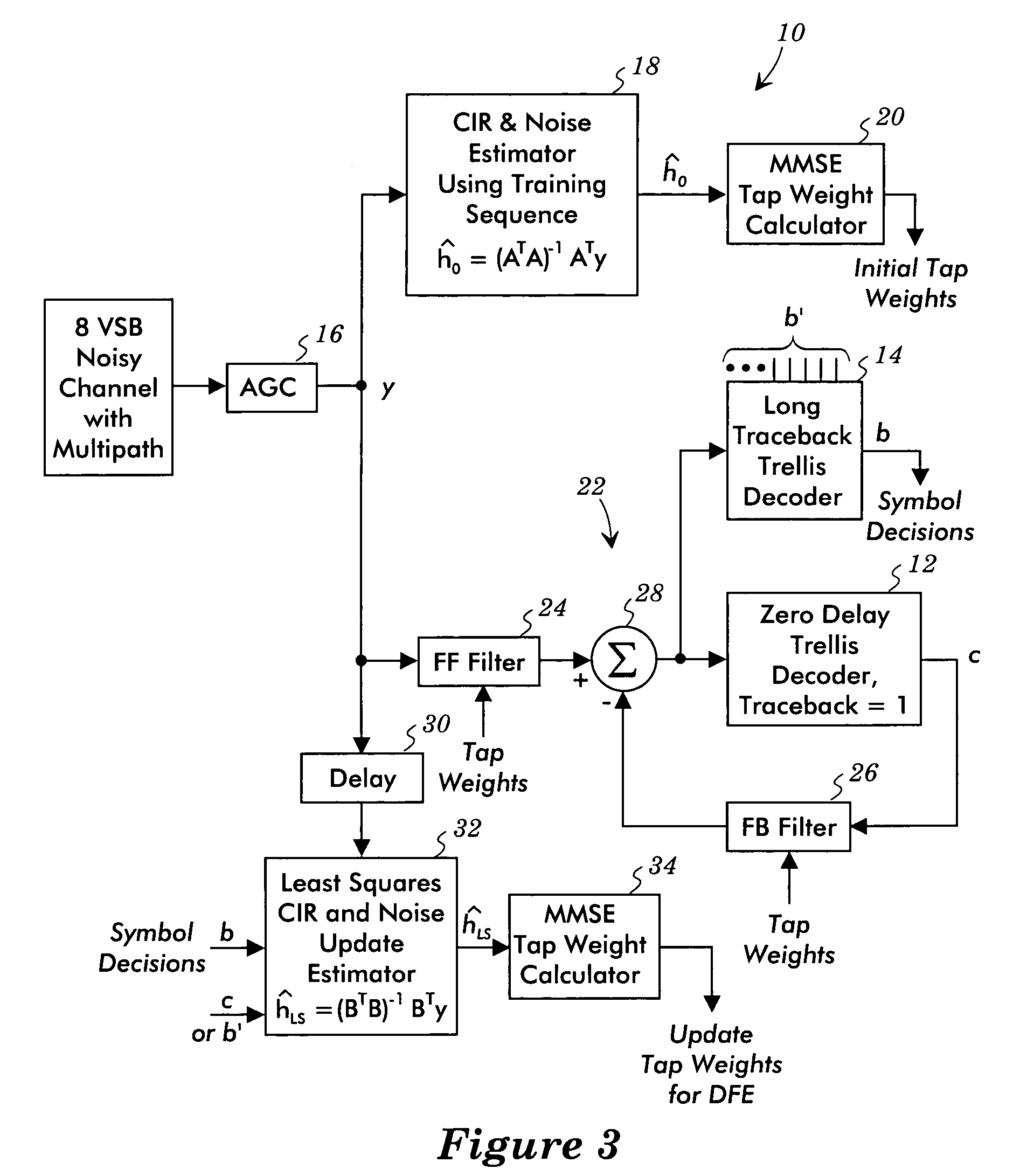
[0022]FIG. 3 illustrates a decision feedback equalizer system 10 that avoids and / or mitigates the convergence and / or tracking problems of previous decision feedback equalizers. The tap weights are calculated based on estimates of the channel impulse response. This arrangement makes use of two decoders, e.g., a short traceback trellis decoder 12 and a long traceback trellis decoder 14. The short traceback trellis decoder 12, for example, may be a zero delay trellis decoder having a traceback depth of one, and the long traceback trellis decoder 14 has a long traceback depth, such as a traceback depth of 32. Theses trellis decoders are 12 phase trellis decoders with a delay equal to 12× (traceback depth−1).
[0023] The signal from the channel is processed by an automatic gain controller 16, which provides the equalizer input signal y. A channel impulse response and noise estimator 18 uses the transmitted training sequence as received in the equalizer input signal y and a stored version ...
PUM
 Abstract
Description
Claims
Application Information