
Schematic diagram generation and display system

Active Publication Date: 2006-04-27
SYNOPSYS INC
View PDF2 Cites 10 Cited by
  • Summary
  • Abstract
  • Description
  • Claims
  • Application Information

AI Technical Summary

Benefits of technology

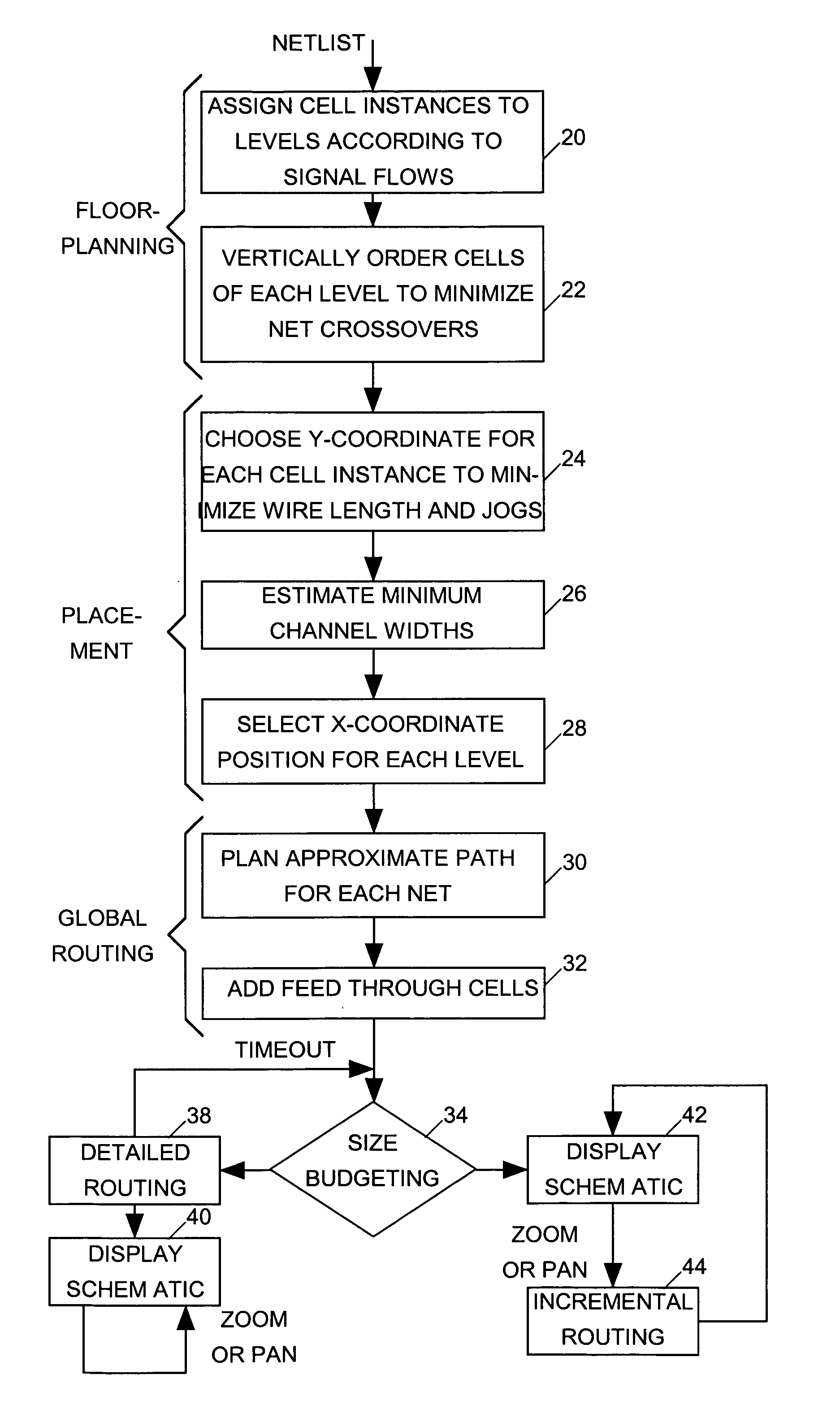
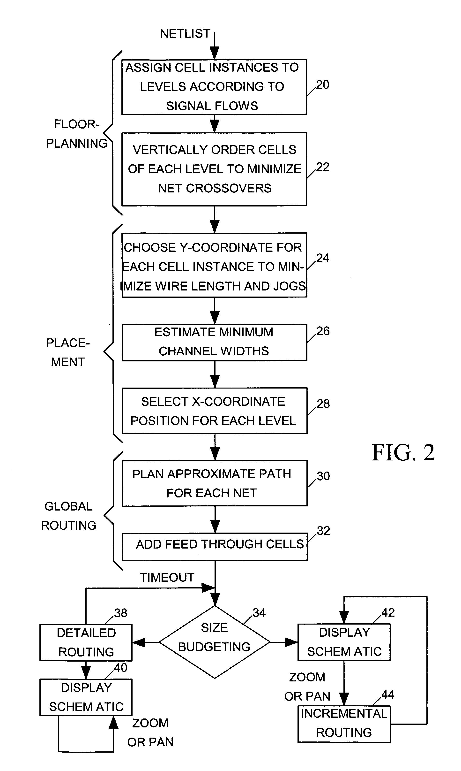
[0013] Thus rather than determining detailed net routing for an entire schematic diagram before generating the schematic display, the system carries out detailed net routing incrementally and “on demand” whenever the user wants to view a new portion of the schematic diagram that the user wants in sufficient detail to distinguish individual nets. Since the time required to carry out detailed routing for a small portion of a schematic diagram is much smaller than the time required to carry out detailed routing for the entire schematic diagram, the user does not perceive long processing delays.

Problems solved by technology

While a netlist makes a suitable input to a circuit simulator or placement and routing tool, it is not always easy for a human to comprehend how signals flow within a circuit by looking only at a text-based netlist model of the circuit.
Display monitors normally do not have sufficient size or resolution to display the entire schematic diagram of a large circuit in a way that representations of cell instances and nets are clearly distinguishable.
One difficulty with prior art schematic diagram generators has been that they often take too long to produce a schematic diagram display for a large IC design.
But this can degrade the quality of the schematic diagram by making it more difficult for a user to trace signal paths through the circuit.
But this “paginated” approach to schematic diagram generation fails to provide a full schematic diagram for the circuit and makes it difficult for a designer to trace signal flows over the entire design by preventing the designer from being able to smoothly pan the schematic diagram.

Method used


Image

  • Schematic diagram generation and display system
  • Schematic diagram generation and display system
  • Schematic diagram generation and display system

Examples


Embodiment Construction

[0017] The present invention relates to software stored on computer-readable media, which when read and executed by a conventional computer causes the computer to generate and display a schematic diagram of a circuit, such and an IC, described by a netlist. Suitable computer-readable media includes, but is not limited to compact disks, floppy disks, hard disk drives, and computer memory, While the specification describes at least one exemplary embodiment of the invention considered a best mode of practicing the invention, the invention is not limited to the particular example(s) described below or to the manner in which they operate.

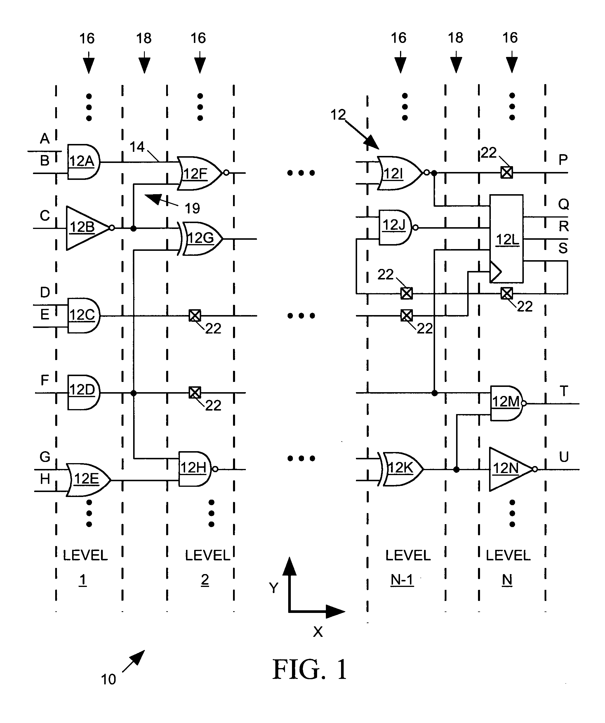
[0018]FIG. 1 is a partial view of a schematic diagram 10 as might be generated and displayed by a conventional computer system programmed by software in accordance with the present invention. Schematic diagram 10 uses symbols as representations 12 of instances of circuit components (“cells”) such as for example logic gates, registers, transistors, and t...


PUM


Abstract

A system for processing a netlist description of a circuit to generate a display of a schematic diagram including representations of cells and nets first determines positions of the cell instance representations within the schematic diagram and then displays the schematic diagram, including the cell instance representations but no representations of the nets. When a user requests a zoom in operation to display a smaller portion of the schematic diagram at a scale at which net representations can be viewed, the system determines routes for representations of nets that are to reside in that portion of the schematic diagram and then displays those net representations upon zooming in to that portion of the schematic diagram. When the user requests a pan operation to shift the display to another portion of the schematic diagram, the system determines routes for representations of nets that are to reside in that other portion of the schematic diagram and then displays those net representations upon panning to that other portion of the schematic diagram

Description

BACKGROUND OF THE INVENTION [0001] 1. Field of the Invention [0002] The invention relates in general to a system for processing a netlist description of a circuit to generate and display a schematic diagram, and in particular to a system that performs net routing on demand as a user zooms and pans the schematic diagram display. [0003] 2. Description of Related Art [0004] An integrated circuit (IC) design engineer typically produces an IC design in the form of a gate level netlist indicating the various components (“cell instances”) to be included in the IC and indicating how their terminals are to be interconnected through nets. The designer can provide a netlist model of an IC as part of a test bench input to a computer-based circuit simulator to determine how the IC described by the netlist will behave, or as input to a placement and routing tool to determine where to place each cell instance within an IC layout and how to route the nets interconnecting the cell instances. [0005] ...

Claims


Application Information

Patent Timeline
IPC IPC(8): G06F17/50G06F9/455
CPCG06F17/50G06F2217/74G06F30/00G06F2111/12
Inventor LIN, PO-HUNGLIN, SHYH-CHANG
Owner SYNOPSYS INC
Learn More