Method for Establishing an Inter-Domain Path that Satisfies Wavelength Continuity Constraint

a technology of inter-domain paths and wavelength continuity constraints, applied in the field of communication technology, can solve the problems of increasing the cost of wavelength converters, reducing the use of wavelength converters, and difficulty in establishing an inter-domain path that satisfies wavelength continuity constraints in multi-domain networks, so as to improve resource utilization, reduce computation delays, and save time in configuring wavelength

Inactive Publication Date: 2012-12-06
UNIV OF ELECTRONICS SCI & TECH OF CHINA
View PDF6 Cites 35 Cited by
  • Summary
  • Abstract
  • Description
  • Claims
  • Application Information

AI Technical Summary

Benefits of technology

[0028]As the cPCEs are independent with each other, they work in parallel in the inter-domain path establishment. Compared with the sequential process way in prior art, it enhanced the resource utilization and decreased computation delay. In addition, when configuring wavelength at each node, i.e reserving the available wavelength, the number of nodes needed to be configured in each domain is small, and the configuration is processed in parallel in each domain, so it saves much time when configuring wavelength. It's noted that though there are much communication signaling between the cPCEs and the fPCE, because of its short delay, the present invention decreased the time delay of inter-domain path establishment generally.

Problems solved by technology

In WDM based wavelength switch optical networks, the wavelength converters are expensive, so decreasing the use of wavelength converters is necessary.
For the consideration of confidentiality and security, each domain maintains internal network information itself, such as network topology and available resources, and conceals them from other domains, which brings that the internal network information of other domain is unknown and only few information on topology and resources is exchanged among domains for confidentiality, computing and configuring, i.e. establishing an inter-domain path that satisfies wavelength continuity constraint in multi-domain network is difficult.
In a dynamic multi-domain optical network, such long time delay on path establishment will seriously decrease the success of path provision, for resources conflict will arise from that long time delay.
For example, the available wavelength detected in path establishment will probably be grabbed by other connections due to the long time delay, and that will ruin the previous efforts.
However, it will take a long time for the node which received the RESV message to reserve wavelength.
So, wavelength reservation will be a long time consuming procedure when the inter-domain path spans more nodes, as shown in FIG. 1 (3), and that will undoubtedly increase the risk of resource conflict.
From the above analysis, it is visible that to inter-domain path establishment, no matter the sequential computation procedure of PCE or the resource reservation, namely wavelength reservation in lower layer, is long time consuming, and wavelength reservation is the main factor of long time delay.
Long time delay can increase the risk of resource conflict and blocking probability of establishment of inter-domain path.

Method used


Image

  • Method for Establishing an Inter-Domain Path that Satisfies Wavelength Continuity Constraint
  • Method for Establishing an Inter-Domain Path that Satisfies Wavelength Continuity Constraint
  • Method for Establishing an Inter-Domain Path that Satisfies Wavelength Continuity Constraint

Examples


embodiment 1

[0039]In one embodiment, as shown in FIG. 2˜FIG. 4, the present invention utilizes hierarchical PCE architecture.

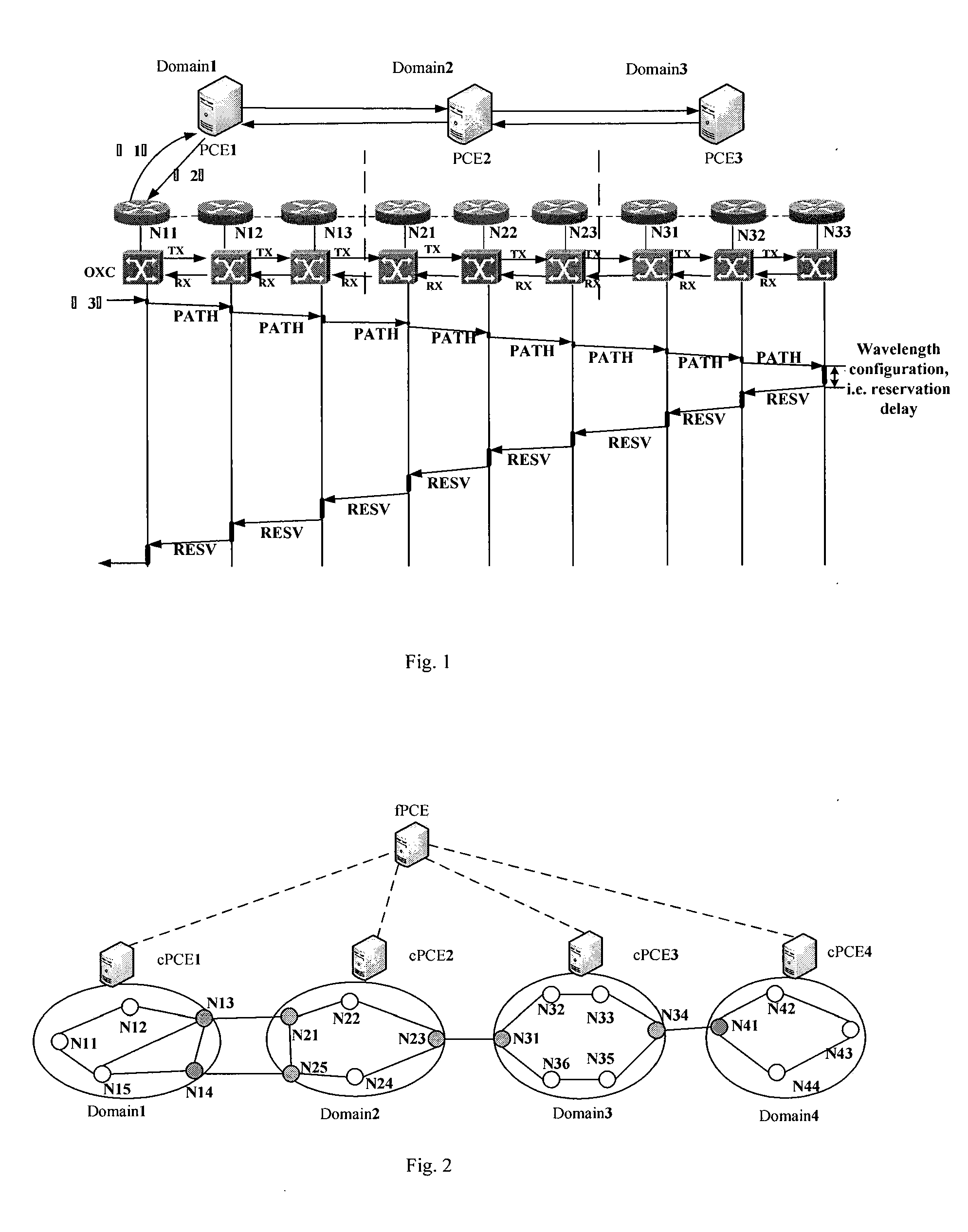
[0040]FIG. 2 is a schematic diagram of the logically hierarchical PCE topology architecture. As shown in FIG. 2, the fPCE is located at up layer, coordinating all cPCEs. The cPCEs are placed at lower layer, responsible for path computing and wavelength checking on path segments.

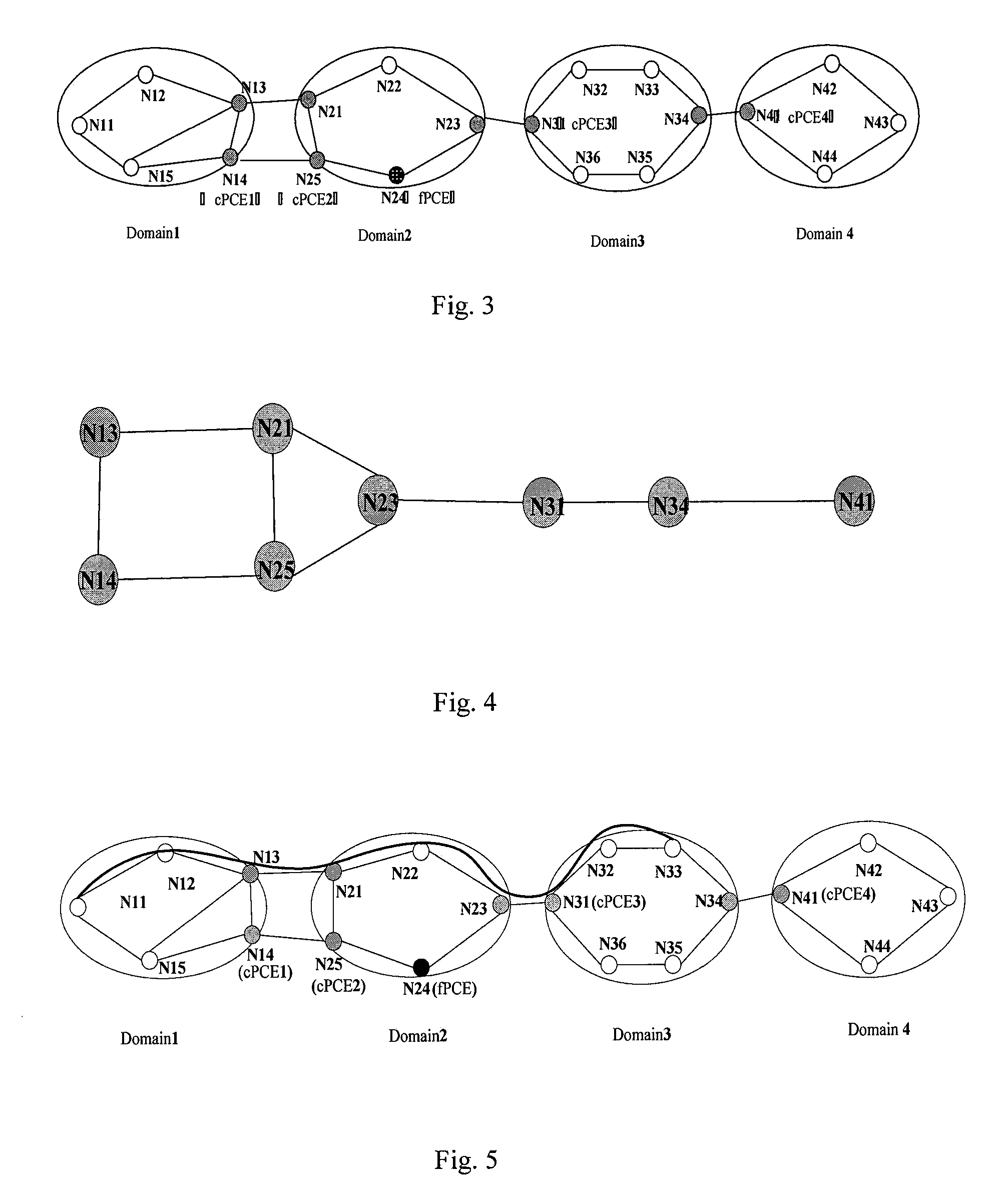
[0041]FIG. 3 is a schematic diagram of the physically hierarchical PCE topology architecture corresponding to FIG. 2. Node N13, N14; N21, N25, N23; N31, N34; N41 are border nodes of Domain1˜4. The cPCEs are placed at border node N14, N25, N31, N41 respectively. The fPCE can be placed at node which locates in middle domain or isolated as an independent device. In this embodiment, the fPCE is placed at node N24 in Domain2. The fPCE maintains a traffic engineering database (TED) which stores a virtual topology architecture comprised by all the border nodes of the domains. It is used to compute abstrac...

embodiment 2

[0055]FIG. 8 is another schematic diagram of the physically hierarchical PCE topology architecture corresponding to FIG. 2 according to one embodiment of the present invention. There are two connection ways between the fPCE and the cPCEs. The first one is indirect connection, in which the fPCE and the cPCEs are placed at some nodes in the network, and they communicates through middle node between them, as shown in FIG. 3 in embodiment 1. The second one is direct connection. The fPCE is isolated from the nodes as an independent device. It connects with each cPCE directly, as shown in FIG. 8. The difference between embodiment 2 and embodiment 1 is the position that the fPCE is placed at. The ways of inter-domain path establishment are the same.


PUM


Abstract

The present invention provides a method for establishing an inter-domain path that satisfies wavelength continuity constraint. The fPCE stores a virtual topology comprised by border nodes of all domains. The present invention uses parallel inter-domain path establishment method to decrease the influence from WCC. Compared with the sequential process way in prior art, it enhanced the resource utilization and decreased computation delay.

Description

CROSS REFERENCED TO RELATED APPLICATIONS[0001]This application claims priority under the Paris Convention to Chinese Patent Application No. 201110146505.5, Filed Jun. 1, 2011, the entirety of which is hereby, incorporated by reference for all purposes as if fully set forth herein.FIELD OF THE INVENTION[0002]The present invention relates to the field of communication technology, more particularly to a method for establishing an hierarchical PCE-based inter-domain path that satisfies wavelength continuity constraint.BACKGROUND OF THE INVENTION[0003]With the development of network technology, the network services grow explosively. And wavelength division multiplexing (WDM) can satisfy the ever-increasing bandwidth demands, so it will be the core technology for future all optical networks undoubtedly.[0004]In WDM based wavelength switch optical networks, the wavelength converters are expensive, so decreasing the use of wavelength converters is necessary. When there are few wavelength co...

Claims


Application Information

Patent Timeline
Patent Type & Authority Applications(United States)
IPC IPC(8): H04B17/00H04L12/753
CPCH04L45/62H04L45/04H04J14/0257H04J14/0286H04J14/0267H04J14/0271H04J14/0284H04J14/0258
Inventor LONG, KEPINGPENG, YUNFENGWANG, ZONGWEICHEN, ZHENWANG, YIN
Owner UNIV OF ELECTRONICS SCI & TECH OF CHINA
Why Eureka
Try Eureka