
Channel impulse response estimating decision feedback equalizer

a decision feedback and channel impulse technology, applied in pulse technique, amplitude demodulation, baseband system details, etc., can solve the problems of multipath interference, long total convergence time of decision feedback equalizer, signal transmitted through channel subject to time varying channel conditions, etc., to achieve short processing delay and long processing delay

Active Publication Date: 2012-11-27
ZENITH F ECTRONICS LLC
View PDF13 Cites 0 Cited by
  • Summary
  • Abstract
  • Description
  • Claims
  • Application Information

AI Technical Summary

Benefits of technology

This approach reduces symbol decision errors and enhances the ability to track time-varying channel conditions, improving the convergence and tracking of the equalizer, thereby enhancing signal reception quality.

Problems solved by technology

The primary obstacle that faces designers in designing receivers so that they achieve good reception is the presence of multipath interference in the broadcast television channel.
In addition, the signal transmitted through the channel is subject to time varying channel conditions due to the movement of the transmitter and signal reflectors, airplane flutter, and, for indoor reception, people walking around the room.
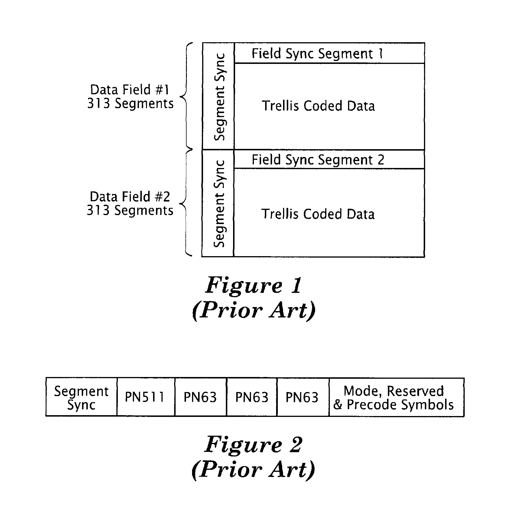
However, because the field sync segment is transmitted relatively infrequently (about every 260,000 symbols), the total convergence time of this equalizer is quite long if the equalizer adapts only on training symbols prior to convergence.
However, use of a symbol slicer results in many symbol decision errors being fed to the feedback filter of the decision feedback equalizer when the channel has significant multipath distortion or a low signal to noise ratio.
These errors give rise to further errors resulting in what is called error propagation within the decision feedback equalizer.
Error propagation greatly degrades the performance of the decision feedback equalizer.

Method used


Image

  • Channel impulse response estimating decision feedback equalizer
  • Channel impulse response estimating decision feedback equalizer
  • Channel impulse response estimating decision feedback equalizer

Examples


Embodiment Construction

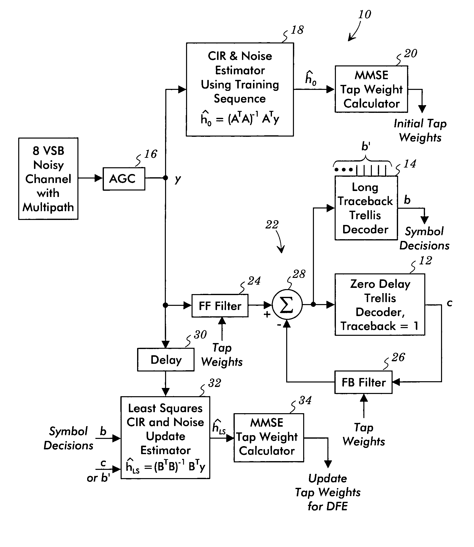
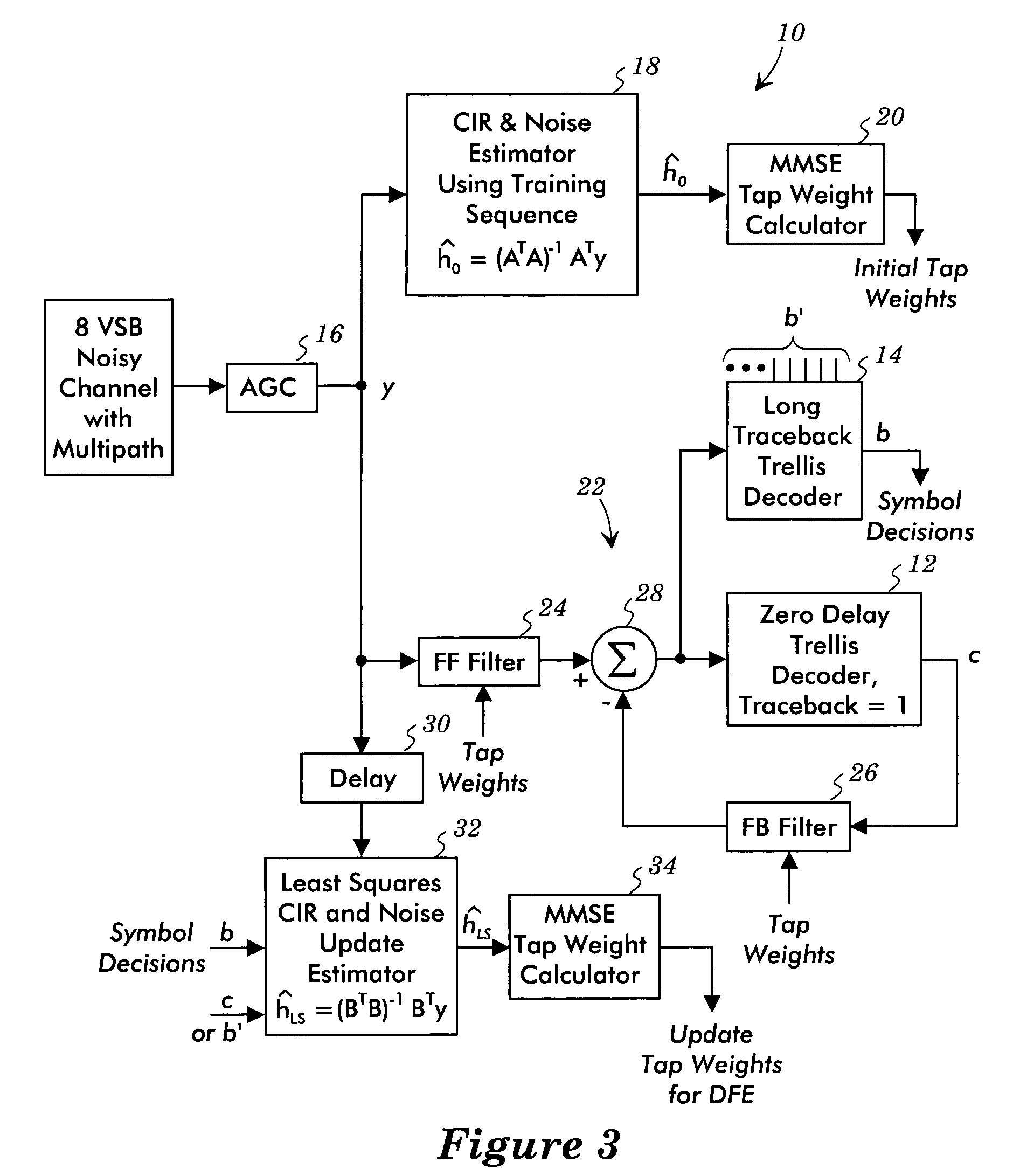
[0022]FIG. 3 illustrates a decision feedback equalizer system 10 that avoids and / or mitigates the convergence and / or tracking problems of previous decision feedback equalizers. The tap weights are calculated based on estimates of the channel impulse response. This arrangement makes use of two decoders, e.g., a short traceback trellis decoder 12 and a long traceback trellis decoder 14. The short traceback trellis decoder 12, for example, may be a zero delay trellis decoder having a traceback depth of one, and the long traceback trellis decoder 14 has a long traceback depth, such as a traceback depth of 32. Theses trellis decoders are 12 phase trellis decoders with a delay equal to 12× (traceback depth−1).

[0023]The signal from the channel is processed by an automatic gain controller 16, which provides the equalizer input signal y. A channel impulse response and noise estimator 18 uses the transmitted training sequence as received in the equalizer input signal y and a stored version of...


PUM


Abstract

A decision feedback equalizer is operated by making first symbol decisions from an output of the decision feedback equalizer such that the first symbol decisions are characterized by a relatively long processing delay, by making second symbol decisions from the output of the decision feedback equalizer such that the second symbol decisions are characterized by a relatively short processing delay, and by determining tap weights for the decision feedback equalizer based on the first and second symbol decisions. The first symbol decisions may be derived from the output of a long traceback trellis decoder. The second symbol decisions may be derived either from the output of a short traceback trellis decoder or from shorter delay outputs of the long traceback trellis decoder.

Description

RELATED APPLICATIONS[0001]This application claims the benefit of U.S. Provisional Application 60 / 571,447 filed on May 14, 2004.TECHNICAL FIELD OF THE INVENTION[0002]The present invention relates to the estimation of channel impulse responses for decision feedback equalizers.BACKGROUND OF THE INVENTION[0003]Since the adoption of the Advanced Television Systems Committee (ATSC) digital television (DTV) standard in 1996, there has been an ongoing effort to improve the design of receivers built for the ATSC DTV signal. The primary obstacle that faces designers in designing receivers so that they achieve good reception is the presence of multipath interference in the broadcast television channel.[0004]The broadcast television channel is a relatively severe multipath environment due to a variety of conditions that are encountered in the channel and at the receiver. Strong interfering signals may arrive at the receiver both before and after the largest amplitude signal. In addition, the si...

Claims


Application Information

Patent Timeline
Patent Type & Authority Patents(United States)
IPC IPC(8): H03H7/30H04L1/00H04L25/03
CPCH04L25/03057H04L2025/03382H04L2025/0349H04B3/04H04L5/12H04L25/03
Inventor AMIZIC, BRUNOFIMOFF, MARKKIM, JINNERAYANURU, SREENIVASA M.
Owner ZENITH F ECTRONICS LLC
Learn More