
Method and apparatus for coding bits of data in parallel

Inactive Publication Date: 2003-05-29
QUALCOMM INC
View PDF0 Cites 36 Cited by
  • Summary
  • Abstract
  • Description
  • Claims
  • Application Information

AI Technical Summary

Benefits of technology

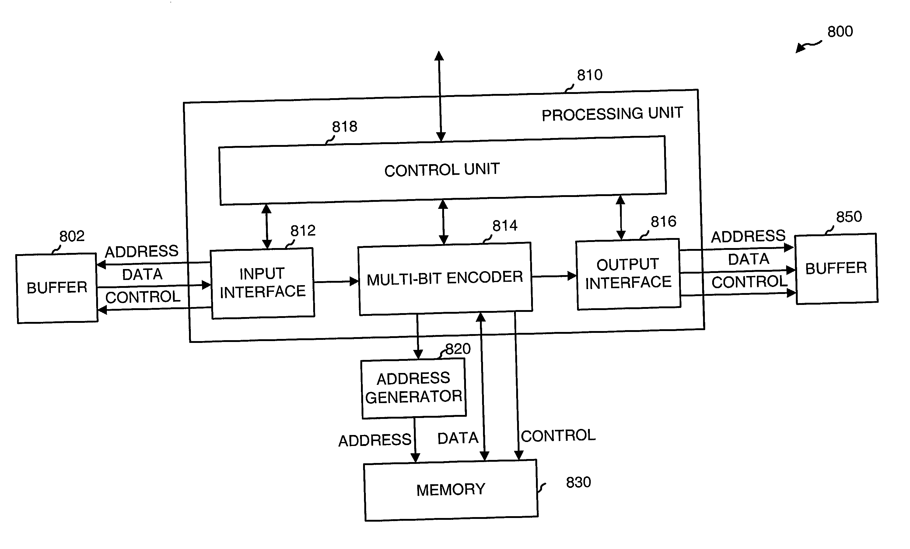
[0119] For the specific design shown in Table 7, the overall coding delays are reduced by a factor of 4.8 for packet format 1 and a factor of 5.0 for packet format 2. It can be observed that further improvement in the processing delays can be achieved by increasing the number of bits to code in parallel, especially for the inner convolutional encoder (i.e., increasing N).
[0120] The shorter processing delays provided by the encoder and interleaver of the present invention provide numerous advantages. Some of these advantages are briefly described below.
[0121] First, shorter processing delays may be used to support certain types of services, such as voice and video, which have more stringent delays requirements. The shorter processing delays may thus allow for use of more efficient coding schemes for delay sensitive applications.
[0122] Second, shorter processing delays can improve system performance. For example, if a particular user or data rate is selected for a particular transmission based on the conditions of the communications link, which are determined at a particular time, shorter processing delays increase the likelihood that the link conditions have not changed by the time of the data transmission. Link conditions typically vary over time, and longer processing delays increase the likelihood that the link conditions have changed by the time of the data transmission, which can then result in degraded performance.
[0123] Third, shorter processing delays can improve the capacity of some communications systems. For example, in the HDR system, power control data is multiplexed with the traffic data and transmitted to the user terminals. Shorter processing delays allow for more accurate control of the transmit power of the user terminals, which can increase the system capacity and improve performance.
[0124] Fourth, shorter processing delays allow sequential sharing of a hardware resource (i.e.,, the encoder) in one processing time slot (i.e., the forward link slot in an HDR system) by multiple transmitting entities (i.e., three users in a three sector system) to reduce the overall area of the hardware design.

Problems solved by technology

However, for improved coding efficiency, it is desirable to process and code larger sized packets, which can result in longer processing delays using the conventional technique that serially codes data.
The long processing delays may adversely impact the performance of the communications system.
If the processing delays are excessively long, the link conditions may have changed by the time of the data transmission, and performance may be compromised or adversely affected.

Method used


Image

  • Method and apparatus for coding bits of data in parallel
  • Method and apparatus for coding bits of data in parallel
  • Method and apparatus for coding bits of data in parallel

Examples


Embodiment Construction

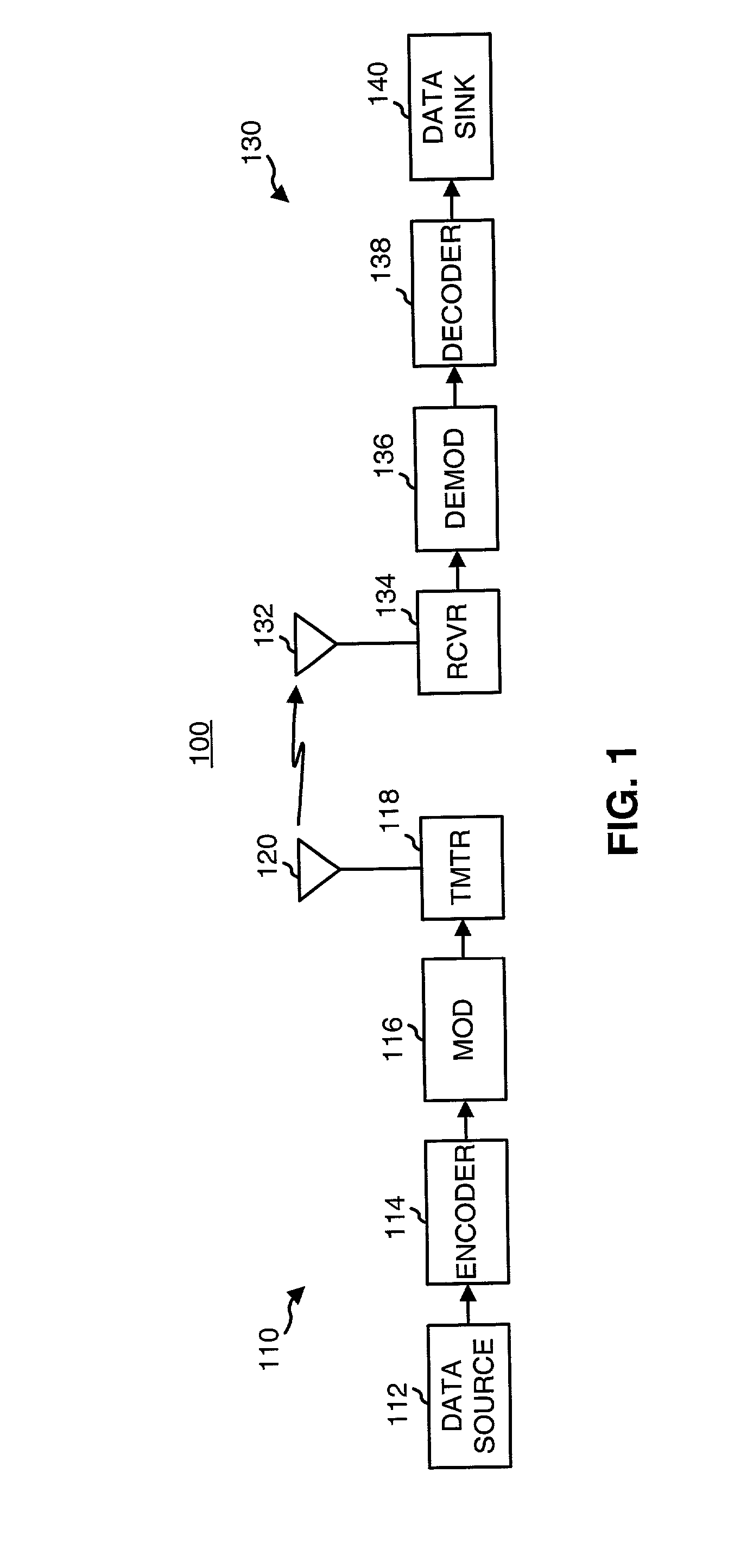
[0033] FIG. 1 is a simplified block diagram of an embodiment of a communications system 100 in which various aspects of the present invention may be implemented. At a transmitter unit 110, traffic data is sent, typically in packets or frames, from a data source 112 to an encoder 114 that formats and codes the data using a particular coding scheme. Encoder 114 typically further performs interleaving (i.e., reordering) of the code bits. A modulator (MOD) 116 then receives, channelizes (i.e., covers), and spreads the coded data to generate symbols that are then converted to one or more analog signals. The analog signals are filtered, (quadrature) modulated, amplified, and upconverted by a transmitter (TMTR) 118 to generate a modulated signal, which is then transmitted via an antenna 120 to one or more receiver units.

[0034] At a receiver unit 130, the transmitted signal is received by an antenna 132 and provided to a receiver (RCVR) 134. Within receiver 134, the received signal is ampli...


PUM


Abstract

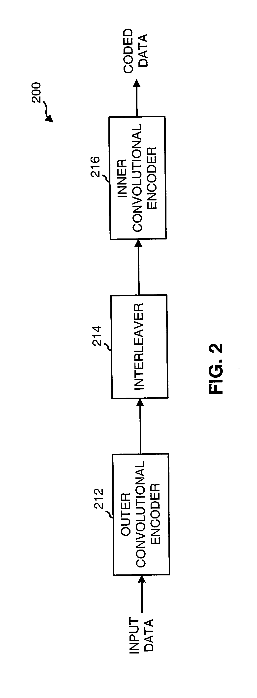
A concatenated encoder capable of coding multiple data bits in parallel and including a first (outer) encoder, a memory, and a second (inner) encoder coupled in cascade. The first encoder receives and codes M data bits in parallel in accordance with a first coding scheme to generate MR code bits. The memory receives and stores unpunctured ones of the MR code bits from the first encoder. The second encoder receives and codes N code bits in parallel in accordance with a second coding scheme to generate coded data. M and N can be any values (e.g., M>=8, N>=4). Each encoder can be a (e.g., a rate ½) convolutional encoder that implements a particular polynomial generator, and can be implemented with one or more look-up tables, a state machine, or some other design.

Description

[0001] I. Field of the Invention[0002] The present invention relates to data communications. More particularly, the present invention relates to coding multiple bits of data in parallel (e.g., using a multiple-port memory) to significantly reduce delays associated with coding.[0003] II. Description of the Related Art[0004] In a typical digital communications system, data is processed, modulated, and conditioned at a transmitter unit to generate a modulated signal that is then transmitted to one or more receiver units. The data processing may include, for example, formatting the data into a particular frame format, coding the formatted data with a particular coding scheme to provide error detection and / or correction at the receiver units, channelizing (i.e., covering) the coded data, and spreading the channelized data over the system bandwidth. The data processing is typically defined by the system or standard being implemented.[0005] At the receiver unit, the transmitted signal is r...

Claims


Application Information

Patent Timeline
IPC IPC(8): H03M13/23H03M13/29H04L1/00
CPCH03M13/23H03M13/29H03M13/6561H03M13/2972H03M13/2903H04L27/26
Inventor SALVI, ROHAN S.HOWARD, MICHAEL A.
Owner QUALCOMM INC
Learn More