Connector port for network interface device

a network interface and connector port technology, applied in the direction of optics, fibre mechanical structures, instruments, etc., can solve the problems of difficult to enter the nid and join the optical fibers of the drop cable, the process of entering the nid and fusion splicing optical fibers is not only time-consuming, and the disconnection or reconfiguration of the existing optical connection is often performed by a highly skilled field technician at significant cost, labor-intensive and therefore costly

Inactive Publication Date: 2005-11-17
CORNING CABLE SYST LLC
View PDF20 Cites 98 Cited by
  • Summary
  • Abstract
  • Description
  • Claims
  • Application Information

AI Technical Summary

Benefits of technology

[0013] In yet another exemplary embodiment, the present invention is a connector port assembly adapted to be located within an external wall of a NID at a subscriber premises for readily connecting and disconnecting a pre-connectorized fiber optic drop cable of an optical communications network. The connector port assembly includes an insert that is positioned in a cable opening defined by the external wall of the NID, a connector receptacle mounted to the insert and a central opening defined by the insert operable for receiving and allowing the pre-connectorized fiber optic drop cable to pass through. The connector port assembly is configured to permit a field technician to readily connect, disconnect and reconfigure an optical connection between the pre-connectorized fiber optic drop cable and a connectorized optical fiber leading from a subscriber's communications equipment.

Problems solved by technology

In particular, it is often difficult to enter the NID and to join the optical fibers of the drop cable with the optical fibers leading from the subscriber's communications equipment using conventional splicing techniques, such as fusion splicing.
In either case, the process of entering the NID and fusion splicing optical fibers is not only time consuming, but frequently must be accomplished by a highly skilled field technician at significant cost and under working conditions in the field that are less than ideal.
Further, once the optical connections are made, it is often labor intensive, and therefore costly, to disconnect or reconfigure the existing optical connections, or to make additional optical connections.

Method used


Image

  • Connector port for network interface device
  • Connector port for network interface device
  • Connector port for network interface device

Examples


Embodiment Construction

[0025] The present invention will now be described more fully hereinafter with reference to the accompanying drawings in which exemplary embodiments of the invention are shown. However, this invention may be embodied in many different forms and should not be construed as limited to the embodiments set forth herein. These exemplary embodiments are provided so that this disclosure will be both thorough and complete, and will fully convey the scope of the invention to those skilled in the art. Like reference numbers refer to like elements throughout the various drawings.

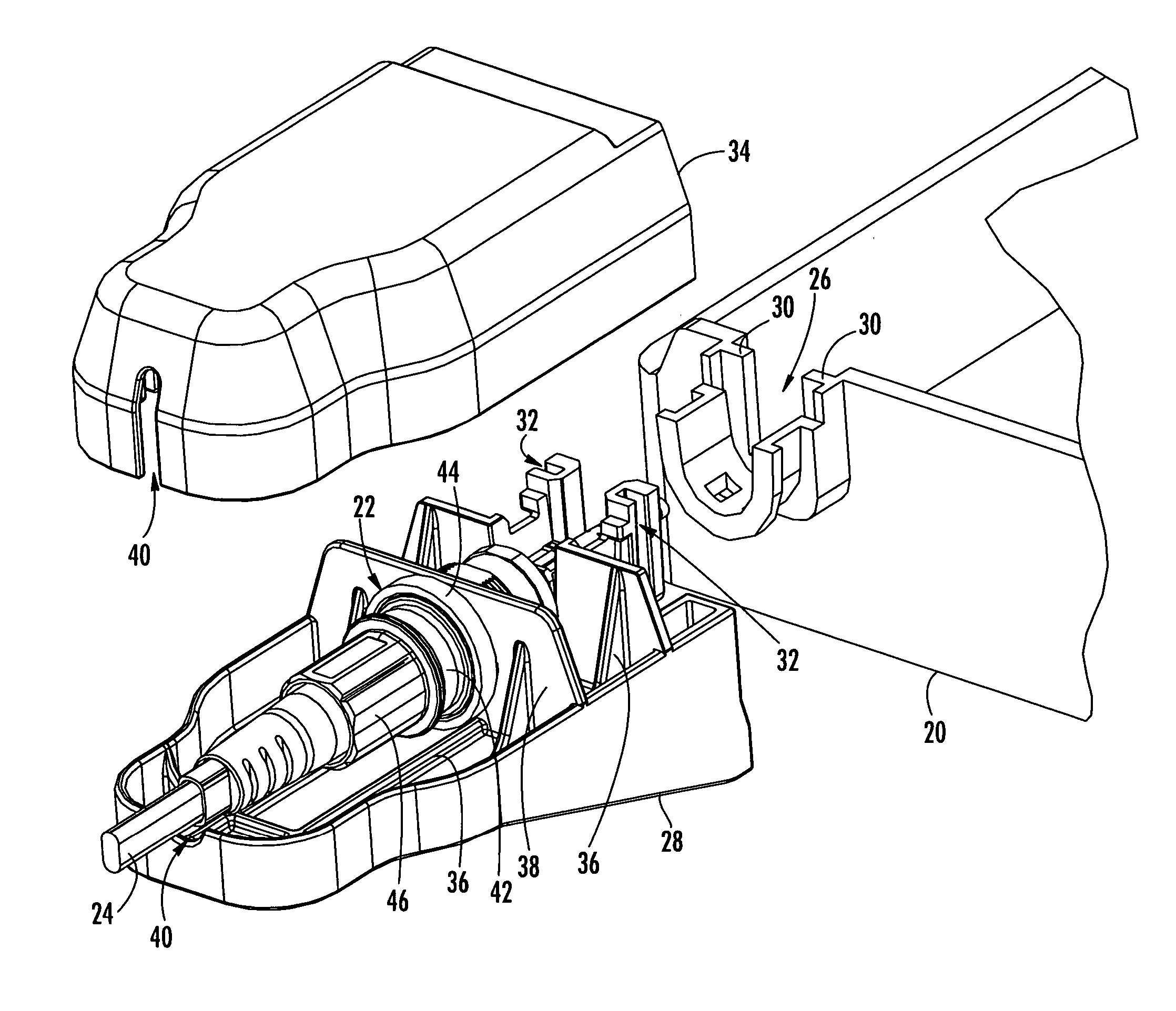
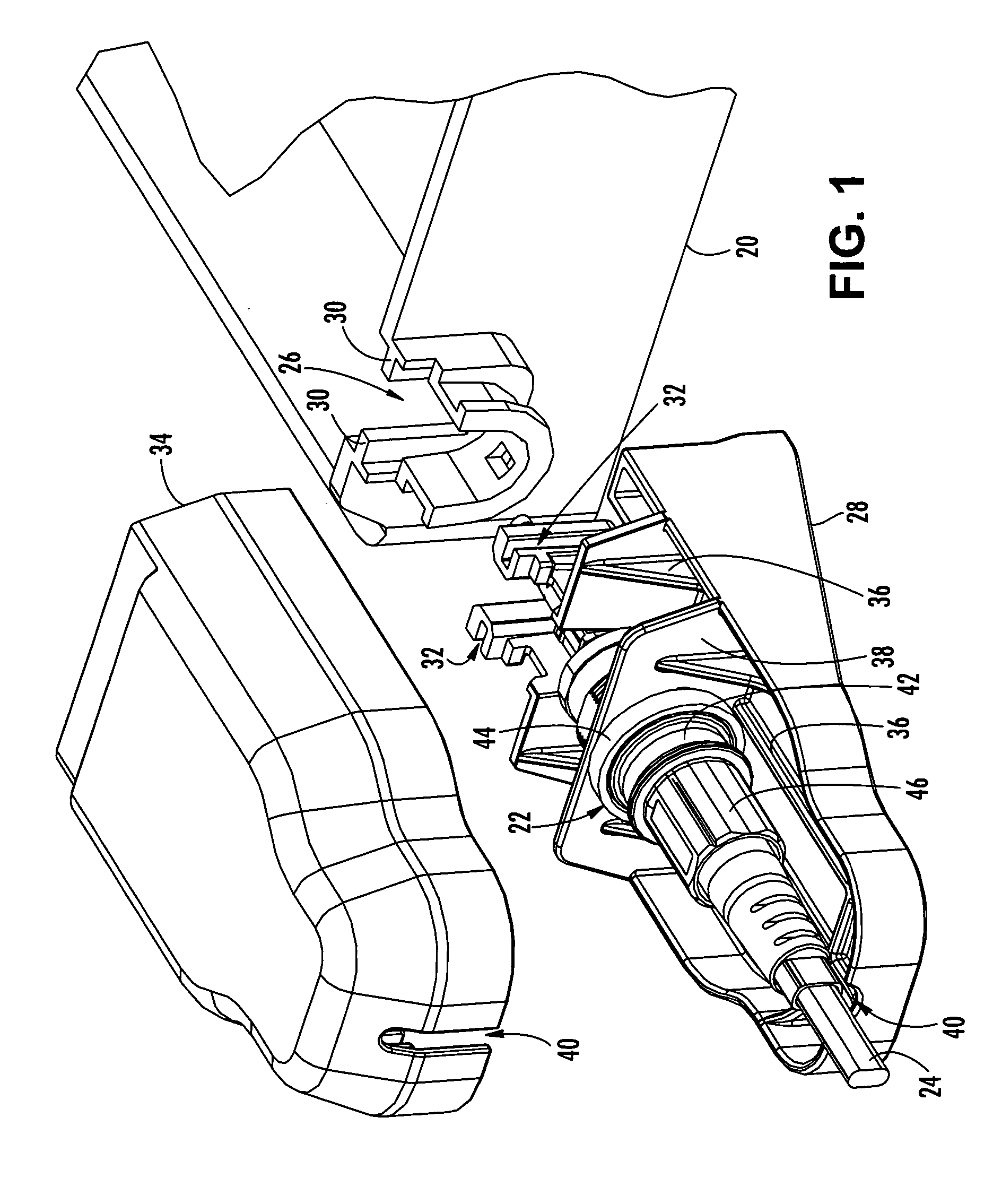
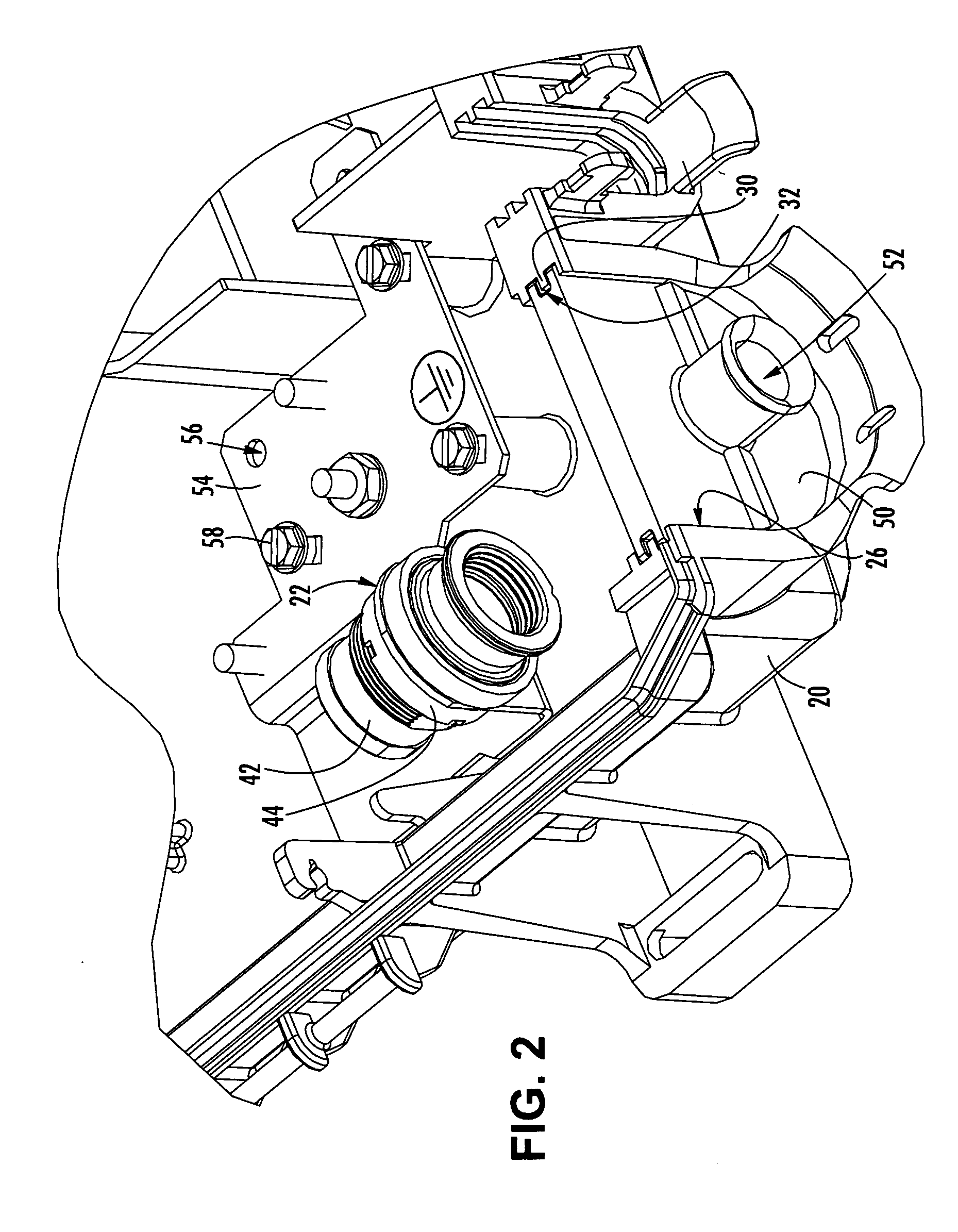
[0026] The present invention provides various exemplary embodiments of a connector port adapted for a network interface device (NID) to receive a connectorized optical fiber from inside the NID and a pre-connectorized fiber optic drop cable from outside the NID. In all embodiments, the connector port is operable for permitting a field technician to readily connect, disconnect or reconfigure a pre-connectorized fiber op...


PUM


Abstract

A connector port is adapted for a (NID) to receive a connectorized optical fiber from inside the NID and a pre-connectorized drop cable from outside the NID. An exterior connector port includes a base positioned within an opening defined by an external wall of the NID, a mount on the base and a connector receptacle secured to the mount adjacent the external wall. An interior connector port includes an insert positioned within an opening defined by an external wall of the NID, a bracket mounted inside the NID and a connector receptacle secured to the bracket. A connector port also includes an insert positioned within an opening defined by a wall of the NID and a connector port secured to the insert. The connector port permits a field technician to readily connect, disconnect and reconfigure optical connections between the connectorized optical fiber and the pre-connectorized drop cable in the field.

Description

RELATED APPLICATIONS [0001] This application is a continuation in part (CIP) of patent application Ser. No. 10 / 784,610, (filed Feb. 23, 2004) and also claims the benefit of provisional patent application Ser. No. 60 / 607,696 (filed Sep. 7, 2004), which are both hereby incorporated in their entireties.BACKGROUND OF THE INVENTION [0002] 1. Field of the Invention [0003] The present invention relates generally to a connector port for use in an optical network, and more particularly, to a connector port adapted for a network interface device (NID) to receive a connectorized optical fiber from inside the NID and a pre-connectorized fiber optic drop cable from outside the NID. [0004] 2. Description of the Related Art [0005] Optical fiber is increasingly being used for a variety of broadband applications including voice, video and data transmissions. As a result of the ever-increasing demand for broadband communications, fiber optic networks typically include a large number of mid-span acces...

Claims


Application Information

Patent Timeline
Patent Type & Authority Applications(United States)
IPC IPC(8): G02B6/36G02B6/38G02B6/42G02B6/44
CPCG02B6/3885G02B6/3893G02B6/4471G02B6/4292G02B6/3897
Inventor FERRETTI, VINCENT E. IIIDEUTSCH, BERNHARD A.BURNS, SCOTT C.KEENUM, JOHN A.
Owner CORNING CABLE SYST LLC
Why Eureka
Try Eureka