ISM band to U-NII band frequency transverter and method of frequency transversion

a frequency transverter and frequency transverter technology, applied in the field of frequency translators, can solve the problems of increasing interference from a variety of devices, overcrowded 900 mhz and 2.4 ghz unlicensed frequencies, and increasing the number of fixed wireless local area networks (lans), so as to reduce the loss tangent, reduce the interference of other wireless devices, and increase channel utilization and reuse

Inactive Publication Date: 2005-11-17
HONEYWELL FED MFG & TECHNOLOGI
View PDF21 Cites 5 Cited by
  • Summary
  • Abstract
  • Description
  • Claims
  • Application Information

AI Technical Summary

Benefits of technology

[0012] In a preferred embodiment, the transverter connects between a conventional data radio and its existing antenna, and comprises a three-terminal bandswitch; a three-terminal input RF isolating device; a three-terminal transmuter; a three-terminal converter; a dual output local oscillator; a three-terminal output RF isolating device; and an antenna. The three-terminal bandswitch allows for selectively connecting the data radio either to the existing antenna at the first frequency band orto the input RF isolating device of the transverter. This selectivity facilitates compatibility with existing legacy systems operating at 2.4 GHz by allowing the user to effectively bypass the transverter when desired.
[0021] It will be appreciated that the transverter of the present invention provides a number of substantial advantages over prior art frequency translators, including making advantageous use of the U-NII band, which increases channel utilization and reuse, mitigates interference from other wireless devices, reduces adjacent channel interference (ACI), and allows for smaller antenna dimensions. Additionally, whereas prior art frequency translators were limited to three channels in simultaneous use at 11 Mbps within a 1000 foot radius using an omni-directional antenna, the transverter advantageously provides more spectrum (300 MHz) and more power and allows for simultaneous use of more than three co-located channels per layer. The transverter advantageously boosts the output power of the existing RF signal from the data radio up to 1 Watt, as allowed for by the FCC, which allows for an increase in transmission range at the second frequency band. Additionally, the transverter advantageously avoids propagation path loss, which could otherwise degrade BER performance, by providing a reduced noise figure in the 5.7 GHz down-converter front end. Additionally, the transverter advantageously provides a phase noise which is lower than that of the data radio, employs additional filtering to minimize spurious products, and uses an oscillator that is significantly more temperature stable than is used in the prior art. Additionally, power reduction criteria are imposed upon directional antennas with a gain above 6 dBi to reduce the potential for multiple devices to compete for spectrum in overlapping areas. Additionally, the transverter connects between an existing data radio and its existing antenna and is therefore advantageously useable with legacy systems without substantial modification. Additionally, whereas the electronic circuitry of prior art translators is packaged near their RF or power source and away from the output antennas, the transverter can be packaged in a housing that also serves as a ground plane of the second frequency band antenna. Additionally, whereas the circuitry of prior art frequency translators is typically constructed using a generic FR-4 PCB material which is undesirably lossy at 6 GHz, the circuitry of the transverter is constructed using a ceramic PTFE substrate material or other material having a comparable dielectric constant. This advantageously reduces the loss tangent by a factor of 12, from 0.027 down to 0.0023. Relatedly, the widths of the RF lines are scaled according to the thickness and permittivity of the substrate material to result in 50 Ohm transmission lines.

Problems solved by technology

As a result, the 900 MHz and 2.4 GHz unlicensed frequencies are becoming increasingly overcrowded and congested.
Thus, fixed wireless local area networks (LANs), for example, involving digitally encoded data modulated onto an RF carrier signal in the 2.4 GHz ISM band, suffer increasing interference from a variety of devices, such as, for example, microwave ovens, cordless telephones, and Bluetooth apparatuses.
Unfortunately, the ISM band is insufficient to allow for wireless transmission of this information within and among these networks.
Unfortunately, prior art frequency translators suffer from a number of problems and disadvantages, including, for example, that they are typically only two-terminal devices and require a different antenna for each frequency band.
Furthermore, though the FCC precludes transmission at both frequency bands simultaneously, no provision is made to maintain a connection at the originating frequency.
Additionally, up / down translation in prior art frequency translators between the first and second frequency bands can result in a phase noise which is undesirably higher than that of the signal's source, and can result in substantial undesirable spurious products.
Additionally, it is well known that multipath levels cause increasing signal deterioration with increasing data rate, particularly at data rates of 10 Mb / s or greater.
Thus, translating to 5 GHz using a prior art frequency translator results in an increase in propagation path loss which could degrade BER performance.
Additionally, they typically do not accommodate or facilitate legacy systems.
Yet another problem encountered when using prior art frequency translators involves potential interference resulting from band-sharing with other non-licensed services.
Additionally, they are typically packaged undesirably near their RF or power source and away from the output antennas.
Additionally, the circuitry of prior art frequency translators is typically constructed using a generic FR-4 PCB material which is undesirably lossy at 6 GHz, making it unsuitable for use in a U-NII band frequency translator.

Method used


Image

  • ISM band to U-NII band frequency transverter and method of frequency transversion
  • ISM band to U-NII band frequency transverter and method of frequency transversion
  • ISM band to U-NII band frequency transverter and method of frequency transversion

Examples


Embodiment Construction

, below.

BRIEF DESCRIPTION OF THE DRAWINGS

[0023] A preferred embodiment of the present invention is described in detail below with reference to the attached drawing figures, wherein:

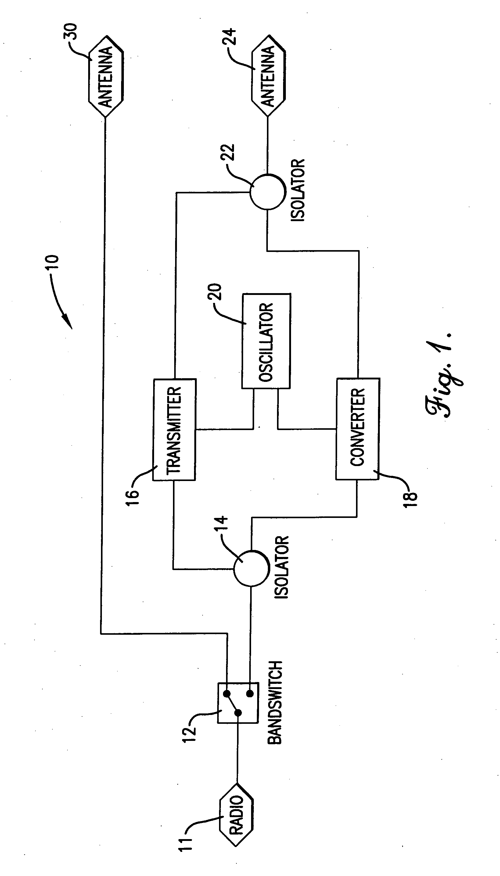
[0024]FIG. 1 is a block diagram of a preferred embodiment of the frequency transverter of the present invention;

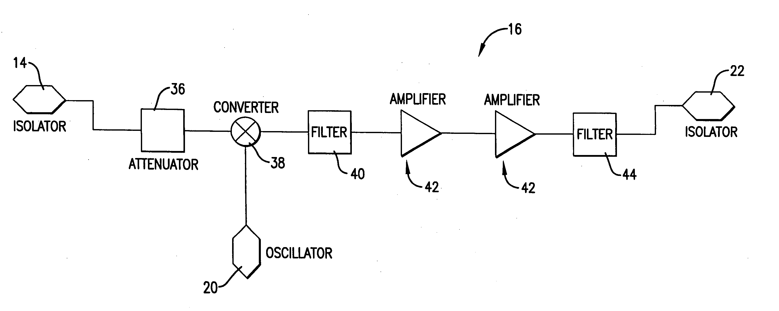
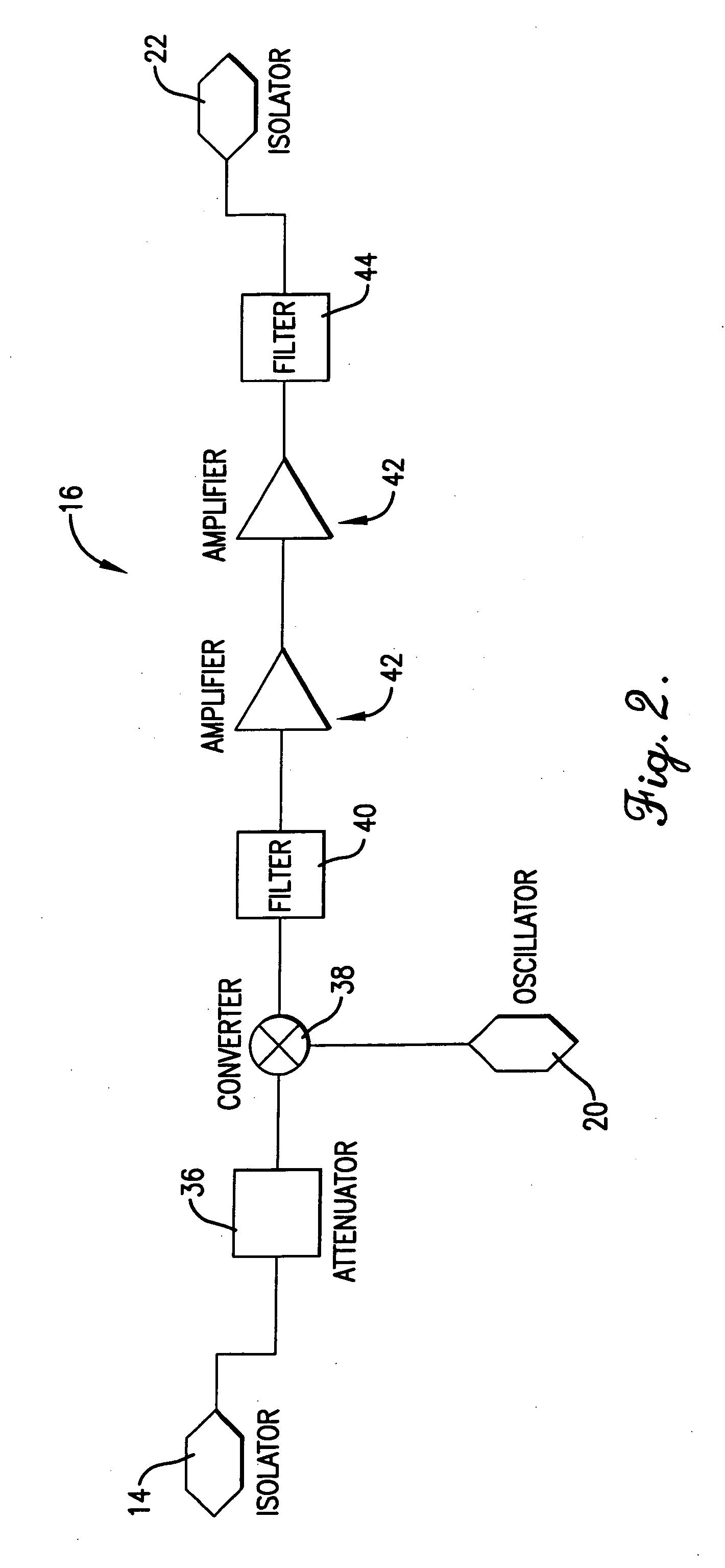
[0025]FIG. 2 is a block diagram of a transmuter component of the frequency transverter of FIG. 1;

[0026]FIG. 3 is a block diagram of a converter component of the frequency transverter of FIG. 1;

[0027]FIG. 4 is a block diagram of a multiplier portion of a local oscillator component of the frequency transverter of FIG. 1;

[0028]FIG. 5 is a block diagram of a fundamental phase-locked-loop portion of the local oscillator component;

[0029]FIG. 6 is a diagram of a wireless communications link setup utilizing the frequency transverter of FIG. 1; and

[0030]FIG. 7 is a block diagram of a fixed communications link setup utilizing the frequency transverter of FIG. 1.

DETAILED DESCRIPTION OF A PREFERRED...


PUM


Abstract

A frequency transverter (10) and method for enabling bi-frequency dual-directional transfer of digitally encoded data on an RF carrier by translating between a crowded or otherwise undesirable first frequency band, such as the 2.4 GHz ISM band, and a less-crowded or otherwise desirable second frequency band, such as the 5.0 GHz-6.0 GHz U-NII band. In a preferred embodiment, the transverter (10) connects between an existing data radio (11) and its existing antenna (30), and comprises a bandswitch (12); an input RF isolating device (14); a transmuter (16); a converter (18); a dual output local oscillator (20); an output RF isolating device (22); and an antenna (24) tuned to the second frequency band. The bandswitch (12) allows for bypassing the transverter (10), thereby facilitating its use with legacy systems. The transmuter (14) and converter (16) are adapted to convert to and from, respectively, the second frequency band.

Description

RELATED APPLICATIONS [0001] The present application is a continuation application and claims priority benefit, with regard to all common subject matter, of earlier-filed U.S. nonprovisional patent application titled “ISM BAND TO U-NII BAND FREQUENCY TRANSVERTER AND METHOD OF FREQUENCY TRANSVERSION,” Ser. No. 10 / 172,151, filed Jun. 14, 2002, and of earlier-filed U.S. provisional patent application titled “ISMUNII TRANSVERTER,” Ser. No. 60 / 298,218, filed Jun. 14, 2001. The identified earlier-filed application is hereby incorporated by reference into the present application.FEDERALLY SPONSORED RESEARCH OR DEVELOPMENT PROGRAM [0002] The present invention was developed with support from the U.S. government under Contract No. DE-AC04-01AL66850 with the U.S. Department of Energy. Accordingly, the U.S. government has certain rights in the present invention.BACKGROUND OF THE INVENTION [0003] 1. Field of the Invention [0004] The present invention relates broadly to frequency translators and m...

Claims


Application Information

Patent Timeline
Patent Type & Authority Applications(United States)
IPC IPC(8): H04B1/00H04B1/26H04B1/40
CPCH04B1/00H04B1/406H04B1/0096H04B1/005
Inventor STEPP, JEFFREY DAVIDHENSLEY, DALE
Owner HONEYWELL FED MFG & TECHNOLOGI
Why Eureka
Try Eureka