Golf club shaft

a golf club and shaft body technology, applied in the field of golf club shafts, can solve the problems of affecting production efficiency, increasing the number of manufacturing steps, and significant bending stress in the grip portion of the shaft body, and achieves the effects of reducing manufacturing costs, reducing manufacturing costs, and improving production efficiency

a golf club and shaft body technology, applied in the field of golf club shafts, can solve the problems of affecting production efficiency, increasing the number of manufacturing steps, and significant bending stress in the grip portion of the shaft body, and achieves the effects of reducing manufacturing costs, reducing manufacturing costs, and improving production efficiency

US20050255935A1Inactive Publication Date: 2005-11-17NIPPON SHAFT

Image

  • Golf club shaft
  • Golf club shaft
  • Golf club shaft

Examples


Embodiment Construction

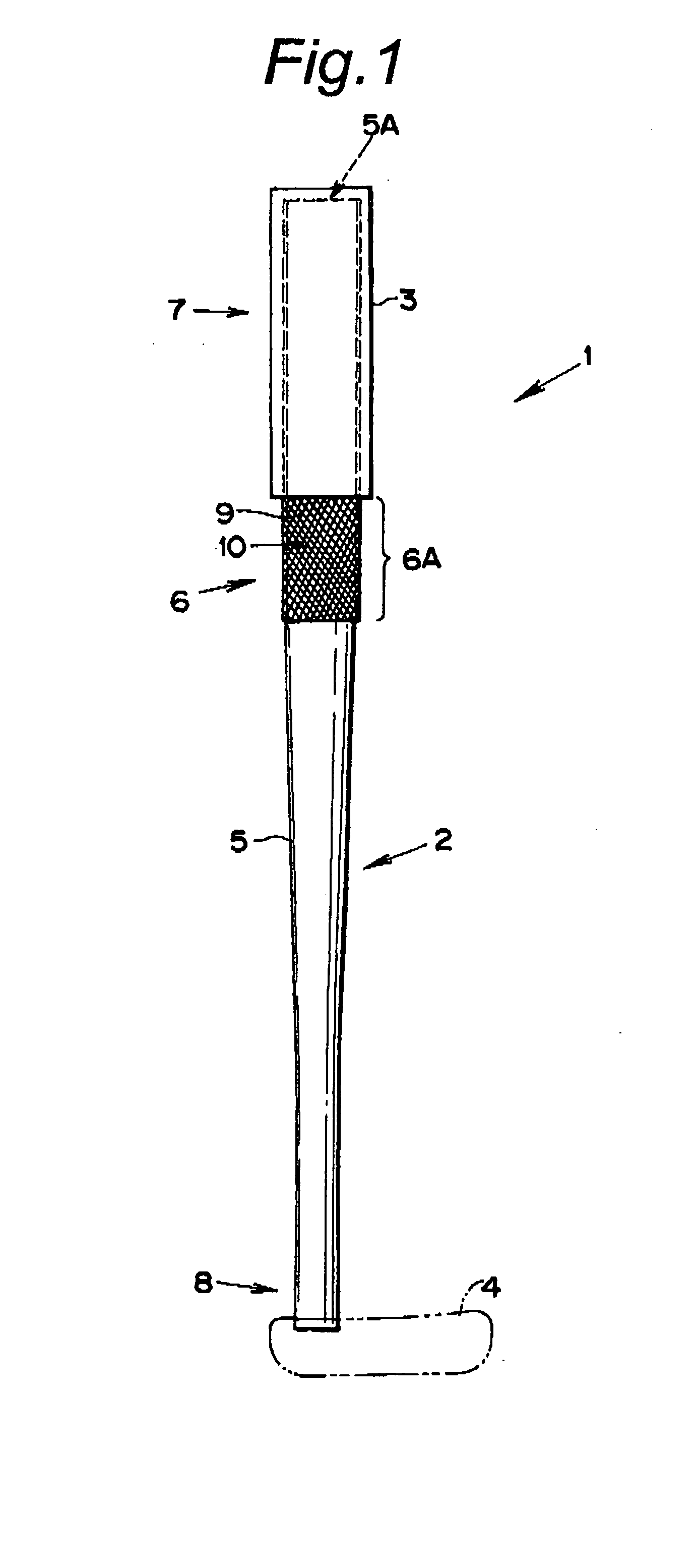
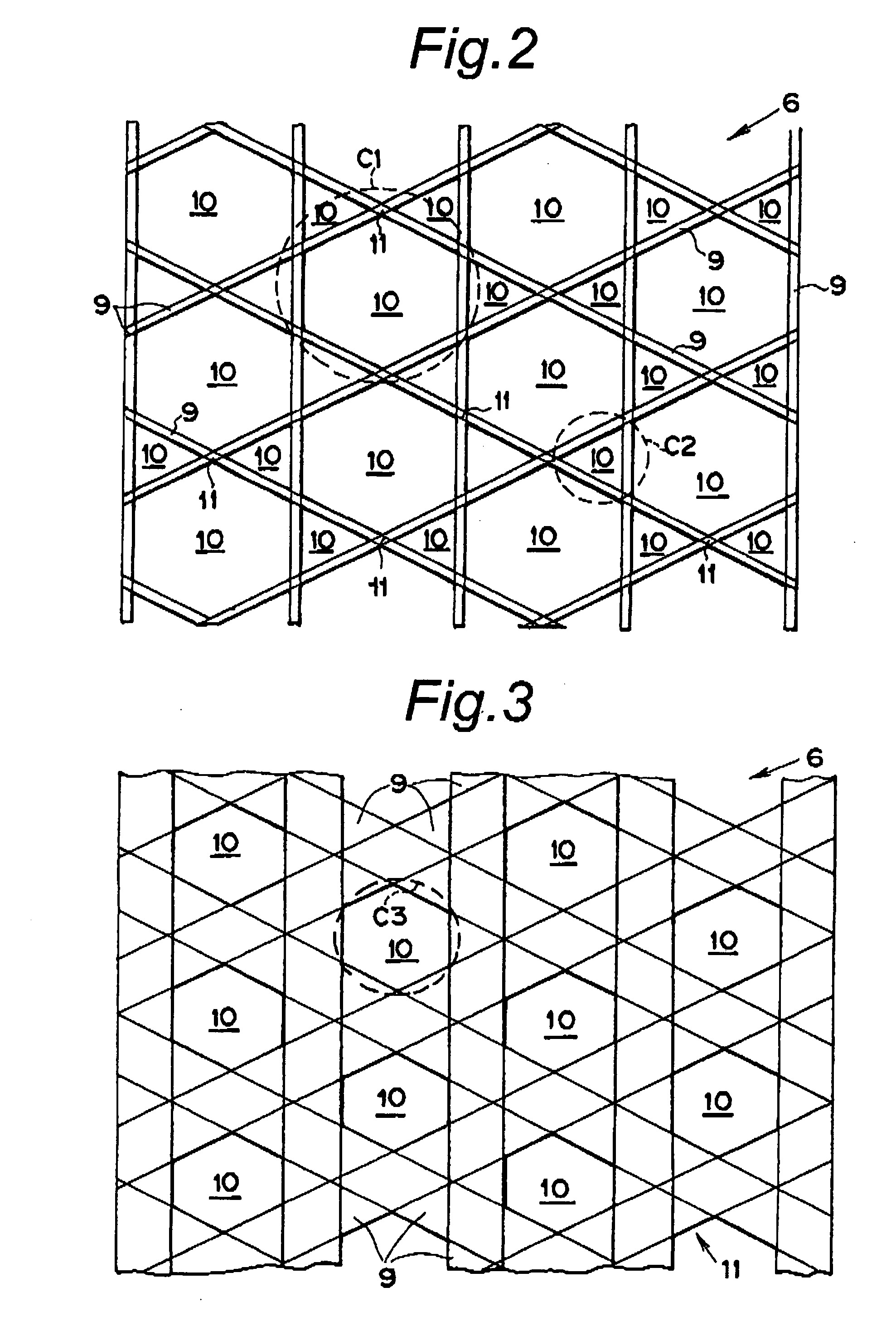
[0049] Since the structure is such that a grip is attached to a steel shaft body by interposing a fiber-reinforced plastic sheet member, that includes a fibrous reinforcing member typically having a reticular (or net-like) structure, the present invention achieves an ultra-lightweight golf club shaft, which enhances the bending strength, flattening strength and vibration damping capabilities of the grip part, and, in addition, improves grip fixability, and makes possible differentiation from the standpoint of appearance as well.

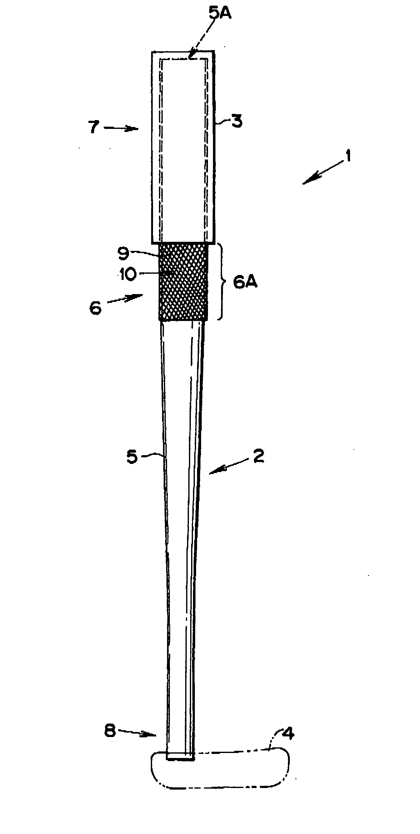
[0050]FIG. 1 is a front view of a golf club 1, and the golf club 1 has a golf club shaft 2, a grip 3 and a club head 4. The golf club shaft 2 has a shaft body 5 and a sheet member 6. The shaft body 5 is formed of steel, and the grip 3 can be mounted to the grip end 7 on one end thereof, and a club head 4 can be mounted to the club head end 8 on the other end thereof.

[0051] The sheet member 6 is secured circumferentially in one continuous turn to the grip en...


PUM


Abstract

The a golf club shaft includes a sheet member made of fiber reinforced plastic material, preferably in the form of a mesh member having a reticular or net-like structure, secured circumferentially around a cylindrical outer surface of the grip end of the shaft body. Preferably, this sheet member includes an extension that is visible from outside by extending from the club head end of the grip to achieve a distinct appearance and / or to enhance the mechanical strength of the related part which is known to be subjected to a substantial stress in use. The presence of the sheet member not only improves various mechanical characteristics, such as the bending strength and flattening strength and the vibration damping capabilities of the grip portion but also provides a distinct and attractive appearance to the golf club.

Description

TECHNICAL FIELD [0001] The present invention relates to a golf club shaft, and more particularly to a golf club shaft that is light in weight and strong. The golf club shaft of the present invention may also have a distinct appearance and allows the firm and reliable attachment of the grip to the shaft body to be ensured. BACKGROUND OF THE INVENTION [0002] A conventional golf club shaft is typically constructed such that, when attaching a grip to the grip end of the shaft body, an adhesive or the like is applied to firmly secure the grip to the shaft body. It is desirable that the bending strength, flattening strength and vibration damping capabilities of the part of the shaft body to which this grip is affixed be improved while the golf club shaft needs to be as light in weight as possible. Furthermore, at the end of the follow through movement in a golfer's golf swing, the grip portion of the shaft body tends to hit the golfer's shoulder, and this causes a significant bending stre...

Claims


Application Information

Patent Timeline
17 Nov 2005
Publication
US20050255935A1
IPC
A63B53/10; A63B53/12; A63B53/14; A63B102/32
CPC
A63B2209/02; A63B53/14; A63B60/54; A63B60/46
Inventors
YANAGISAWA, KAZUAKI; HOSODA, KEIJI