Hydraulic clutch state diagnostic and control

Inactive Publication Date: 2005-11-17
GM GLOBAL TECH OPERATIONS LLC
View PDF1 Cites 156 Cited by
  • Summary
  • Abstract
  • Description
  • Claims
  • Application Information

AI Technical Summary

Benefits of technology

[0007] The present invention indicates clutch application subsequent to issuance of a clutch apply command which effects fluid pressure changes in a clutch control chamber. When a clutch apply command is issued an historical clutch apply time previously recorded is accessed. Clutch apply fluid pressure is monitored to provide an apply signal indicative of clutch application as a function of clutch apply fluid pressure and a release signal indicative of clutch release as a function of clutch apply fluid pressure. Clutch application is indicated upon the first to occur of the pressure monitor providing the apply signal and the historical clutch apply time being exceeded.
[0008] Provided is a method for indicating clutch state change in a clutch system including a clutch fluidically applied in accordance with fluid pressure in a control chamber. The method includes providing a fluid pressure based clutch state switch characterized by a respective first state signal indicating clutch application and a respective second state signal indicating cl

Problems solved by technology

Inaccuracy in clutch state knowledge can result in excessive and premature clutch wear.
Additionally, loss of clutch state knowledge can result in significantly reduced vehicle performance since substantial compromises in shift controls may need to be made absent such

Method used


Image

  • Hydraulic clutch state diagnostic and control
  • Hydraulic clutch state diagnostic and control
  • Hydraulic clutch state diagnostic and control

Examples


Embodiment Construction

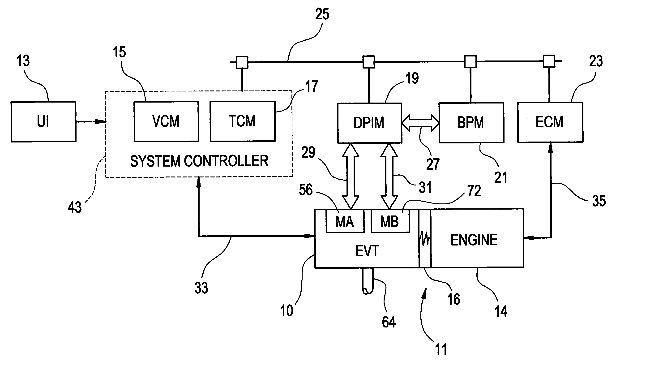
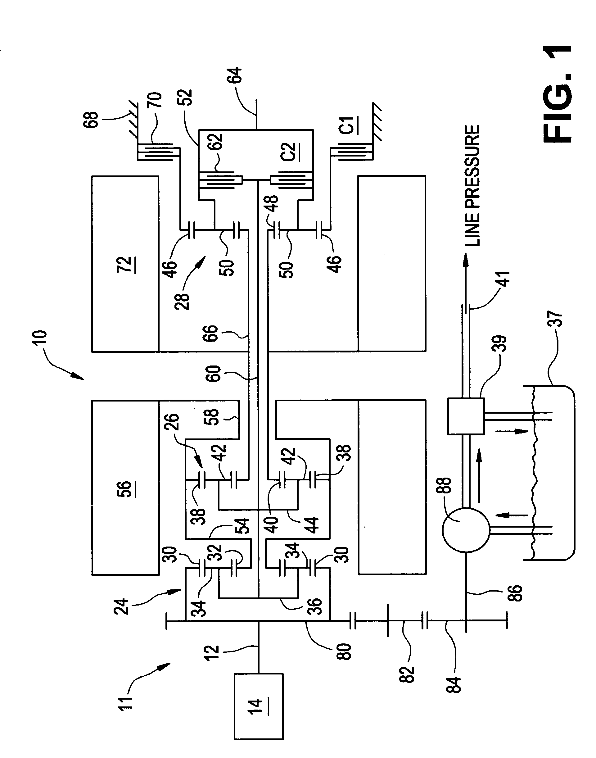
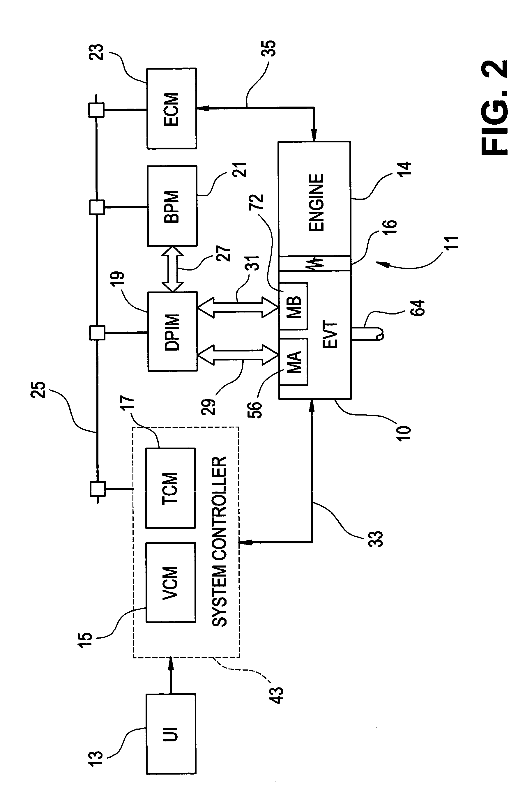
[0020] With reference first to FIGS. 1 and 2, a vehicular powertrain system is generally designated 1. Included in the powertrain 11 is one representative form of a multi-mode, compound-split, electrically variable transmission (EVT) particularly suited for implementing the controls of the present invention and designated generally by the numeral 10 in FIGS. 1 and 2. With particular reference, then, to those figures, the EVT 10 has an input member 12 that may be in the nature of a shaft which may be directly driven by an engine 14 or, as shown in FIG. 2, a transient torque damper 16 may be incorporated between the output member of the engine 14 and the input member of the EVT 10. The transient torque damper 16 may incorporate, or be employed in conjunction with, a torque transfer device (not shown) to permit selective engagement of the engine 14 with the EVT 10, but it must be understood that such a torque transfer device is not utilized to change, or control, the mode in which the ...


PUM


Abstract

Clutch engagement is preferably determined in accordance with monitored pressure conditions within a clutch control chamber. Clutch slip is monitored and information respecting clutch engagement inferred therefrom is stored for subsequent retrieval and use in a redundant slip based clutch engagement determination. Clutch slip is also monitored for information respecting clutch disengagement for use in a redundant slip based clutch disengagement determination.

Description

TECHNICAL FIELD [0001] The present invention is related to vehicular transmissions. More particularly, the invention is concerned with determination of hydraulic clutch apply and release states in a vehicular transmission. BACKGROUND OF THE INVENTION [0002] Vehicular powertrains commonly include conventional multi-ratio, automatic transmissions and electro-hydraulic controls for effecting speed ratio changes or gear shifts. Controllable torque transfer devices, commonly clutch packs or band clutches, are utilized to transfer torques between planetary gearset members to effect speed ratio changes. Each such shift typically comprises at least one oncoming clutch application or offgoing clutch release. Often times, at least one offgoing clutch release and one oncoming clutch application is associated with a speed ratio change. [0003] Clutch apply and release timings are critical to effective speed ratio shift control. Accurate knowledge of clutch apply or release state can significantl...

Claims


Application Information

Patent Timeline
IPC IPC(8): F16D48/02F16D48/06G06F17/00
CPCB60W10/02F16D48/066F16D2500/1087F16D2500/3024F16H2059/6807F16D2500/30406F16D2500/3166F16D2500/70406F16H61/061F16D2500/30401
Inventor SAH, JY-JEN F.STEINMETZ, TODD M.
Owner GM GLOBAL TECH OPERATIONS LLC
Why Eureka
Try Eureka