Hydraulic bale ramp

Inactive Publication Date: 2005-11-24
CNH IND AMERICA LLC
View PDF22 Cites 31 Cited by
  • Summary
  • Abstract
  • Description
  • Claims
  • Application Information

AI Technical Summary

Benefits of technology

[0018] Thus a need has evolved for a bale discharge apparatus which performs several desirable functions. Principally, such an apparatus should deposit a bale on the ground, at a desired position rearward of where it would be if it simply fell from the rear of the baler. Also, it should retain the discharged bale at the desired discharge position while the tailgate of the baler closes, thereby preventing the tailgate from coming into contact with a discharged bale. Fu

Problems solved by technology

The stopping, backing up, and restarting steps, along with the increasingly larger size of the baling machines, have generated growing concerns.
Third, he opens the tailgate.
Failure to back-up, during the sequence, results in considerable unbaled crop stock being left on the ground.
However, on some terrain, backing up the baler causes tailgate damage, by a previously discharged bale striking the tailgate.
Although conveyors can work the bales further away from the baler than can ramps, the mechanism can be expensive and cumbersome.
The above-described prior art ejection components, as previously stated, do not completely solve the problems of bale discharge.
While basically a simple device, the kicker mechanisms require springs of great strength in order to provide a rolling impetus to a bale which may weigh as much as 1500 lbs., and even then may fail to move the bale far enough away from the baler.
This can result in loud clanging noises as the

Method used


Image

  • Hydraulic bale ramp
  • Hydraulic bale ramp
  • Hydraulic bale ramp

Examples


Embodiment Construction

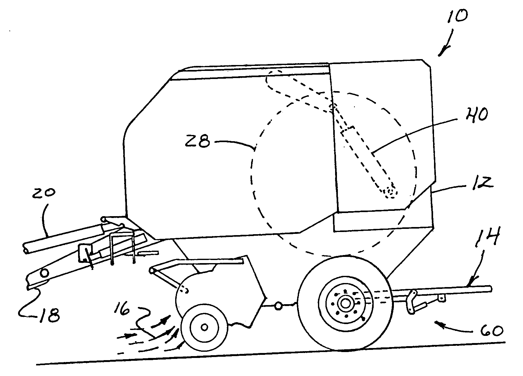
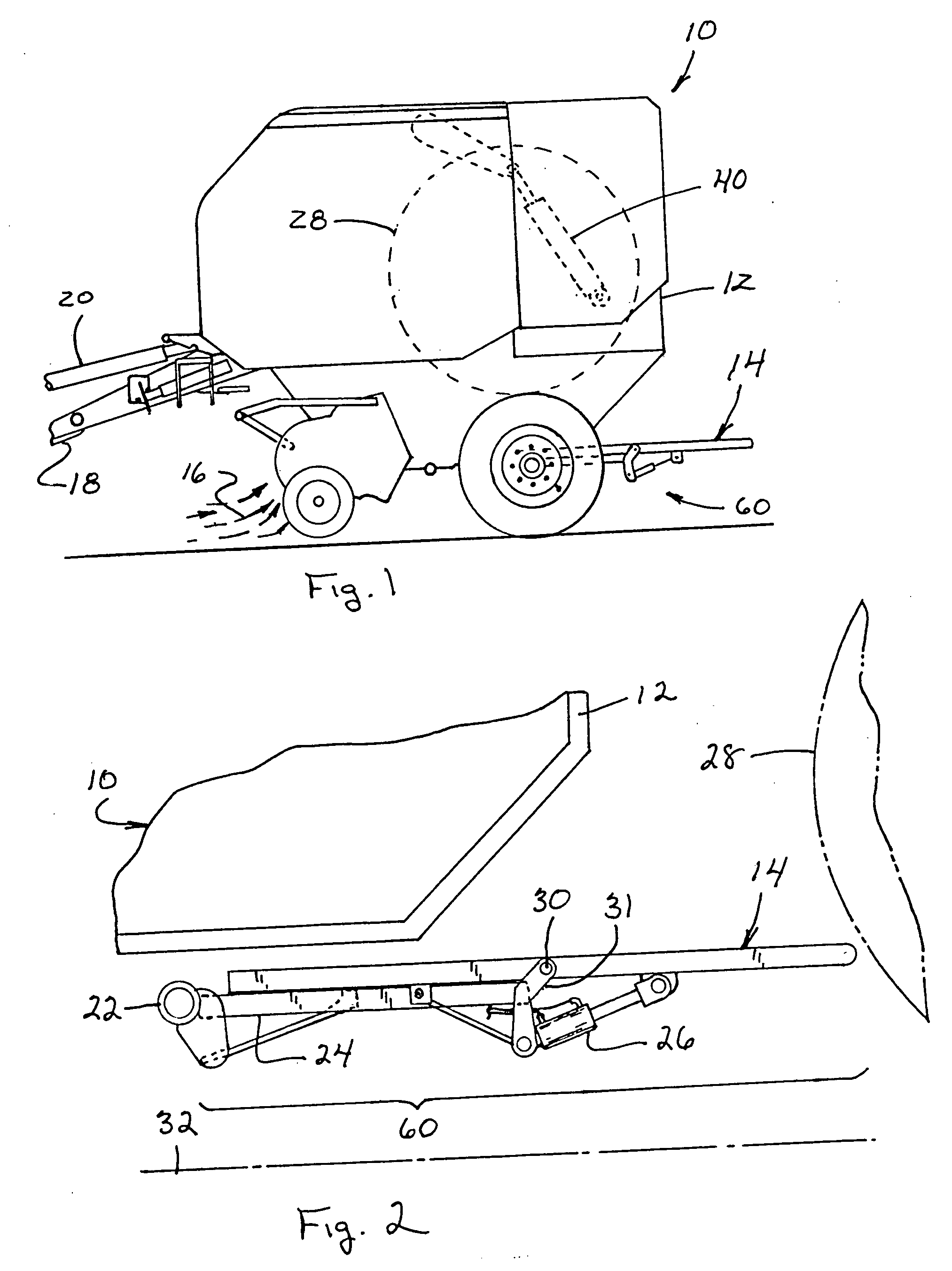
[0032] Referring to the drawings in detail, FIG. 1 shows the apparatus of the present invention. A baler 10, commonly known as a round baler, which is towed behind, for example, a tractor (not shown) by way of hitch 18, is powered by the power take off shaft 20. Fodder 16 is fed into the baler 10 and the fodder 16 is formed into a cylindrical bale 28, as by rolling action. The baler 10 also wraps the bale 28 with, for example, plastic, foil, or if possible wire wrapping material (not shown).

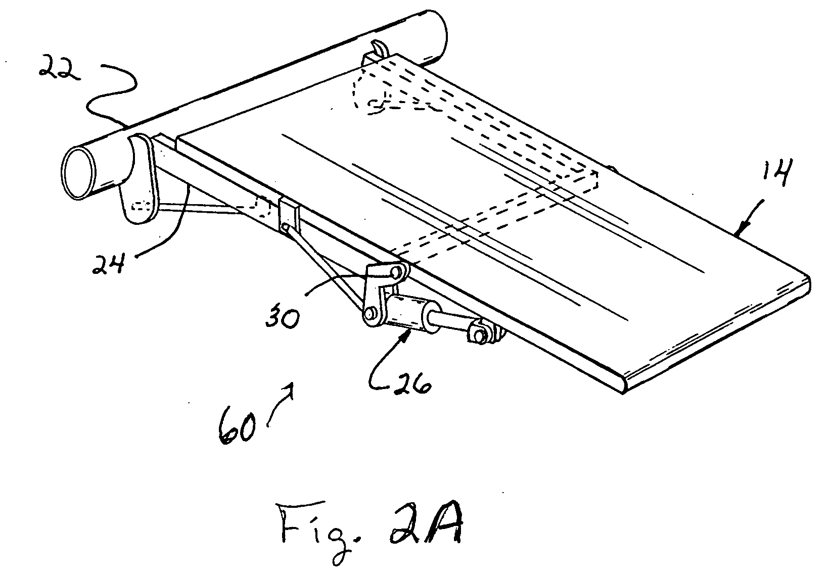
[0033] After bale 28 has been formed to a predetermined size, the baling mechanism of baler 10 is stopped, and the tailgate 12 is actuated by piston cylinder 40, to begin opening up by rotation about a pivot point 38 (shown in FIG. 3). Consequently, bale 28 is discharged out of baler 10, and onto the bale ramp 14 (FIG. 6) component of ejection element 60 (FIG. 2A). Bale ramp 14 has a length extending beyond the back of the tailgate and said ramp is rotatably attached to racket 31 at pivot point ...


PUM


Abstract

An improved round baler having a weight-balanced discharge ramp which pivots hydraulically from a dump position to a home position where it protects the baler's tailgate from damage.

Description

[0001] This application is a continuation-in-part of U.S. patent application Ser. No. 10 / 816,993, filed Apr. 1, 2004.TECHNICAL FIELD [0002] This invention relates generally to round balers, for converting loose crop stock or fodder into cylindrical bales. The invention particularly relates to ejection components, which discharge or eject the bales from the baler. BACKGROUND ART [0003] Round balers for crop stock such as clover or alfalfa hay, have long been known in the art. These machines are employed after the crop stock is mowed and gathered into a windrow. Customarily, the balers are driven down the windrow, from which it intakes the crop fodder, forms a cylindrically configured bale in a bale-forming chamber, and then discharges the bale from the baler. The balers can be either self-propelled or pulled by, for example, a farm tractor. [0004] Previously, round bales could be easily handled, manually. Such bales were two feet long cylindrical rolls, had a maximum diameter of less...

Claims


Application Information

Patent Timeline
IPC IPC(8): A01D39/00A01D43/02A01D75/00A01F15/08
CPCA01F15/0883
Inventor SMITH, KEVIN M.FYOCK, MICHAELMCINTOSH, SEANMECKLEY, DANIELUNGER, JOHN
Owner CNH IND AMERICA LLC
Why Eureka
Try Eureka