Vehicle door structure

a technology for doors and vehicles, applied in the field of vehicle door structures, can solve the problems that the reinforcement beam may not be able to effectively perform its function, and achieve the effects of avoiding deformation of the door structure, reducing the reaction force, and effectively absorbing the energy of the side crash

Active Publication Date: 2014-05-20
HONDA MOTOR CO LTD
View PDF17 Cites 9 Cited by
  • Summary
  • Abstract
  • Description
  • Claims
  • Application Information

AI Technical Summary

Benefits of technology

[0012]According to the vehicle door structure of the present invention, as the beam member is not provided with a closed cross section, but comprises a S shaped cross section member, the beam member is able to fully collapse into a flat state without leaving any uncollapsed part when subjected to a side crash load. Thereby, the energy of the side crash can be effectively absorbed. As the upper C shaped channel section of the S shaped cross section member of the beam member extends along the lower edge of the window opening, the upper C shaped channel section is located significantly away from the center of the bending moment caused by a frontal crash. Thereby, the upper C shaped channel section is enabled to support the bending moment of the frontal crash with a minimum reaction force, and the deformation of the door structure can be avoided in a reliable manner. A hinge is attached to a pillar located immediately ahead of the door, and the hinge creates a relatively stiff part owing to the property thereof and / or the property of the surrounding part. (This pillar consists of an A pillar provided in a front end part of the passenger compartment when the door consists of a front door, and a B pillar provided in an intermediate part of the passenger compartment when the door consists of a rear door.) Therefore, by placing the front part of the lower C shaped channel section at a same elevation as the hinge that connects the vehicle door to the vehicle body at the front end of the door, the frontal crash load can be directly transmitted from the hinge to the beam member as a fore and aft axial force so that the frontal crash load can be favorably transmitted to the rear part of the vehicle body by the beam member serving as a load path member, and the deformation of the door structure can be avoided.
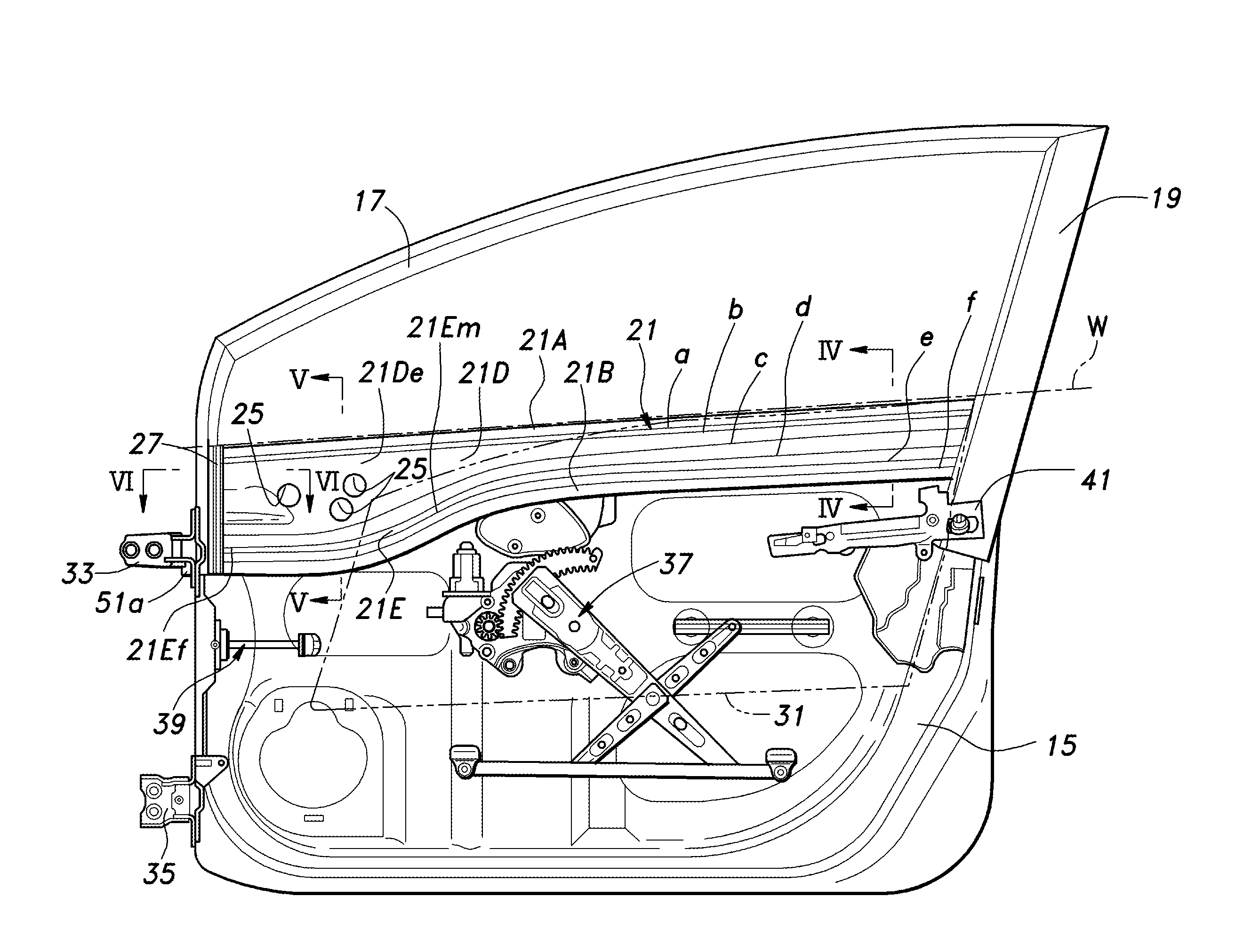
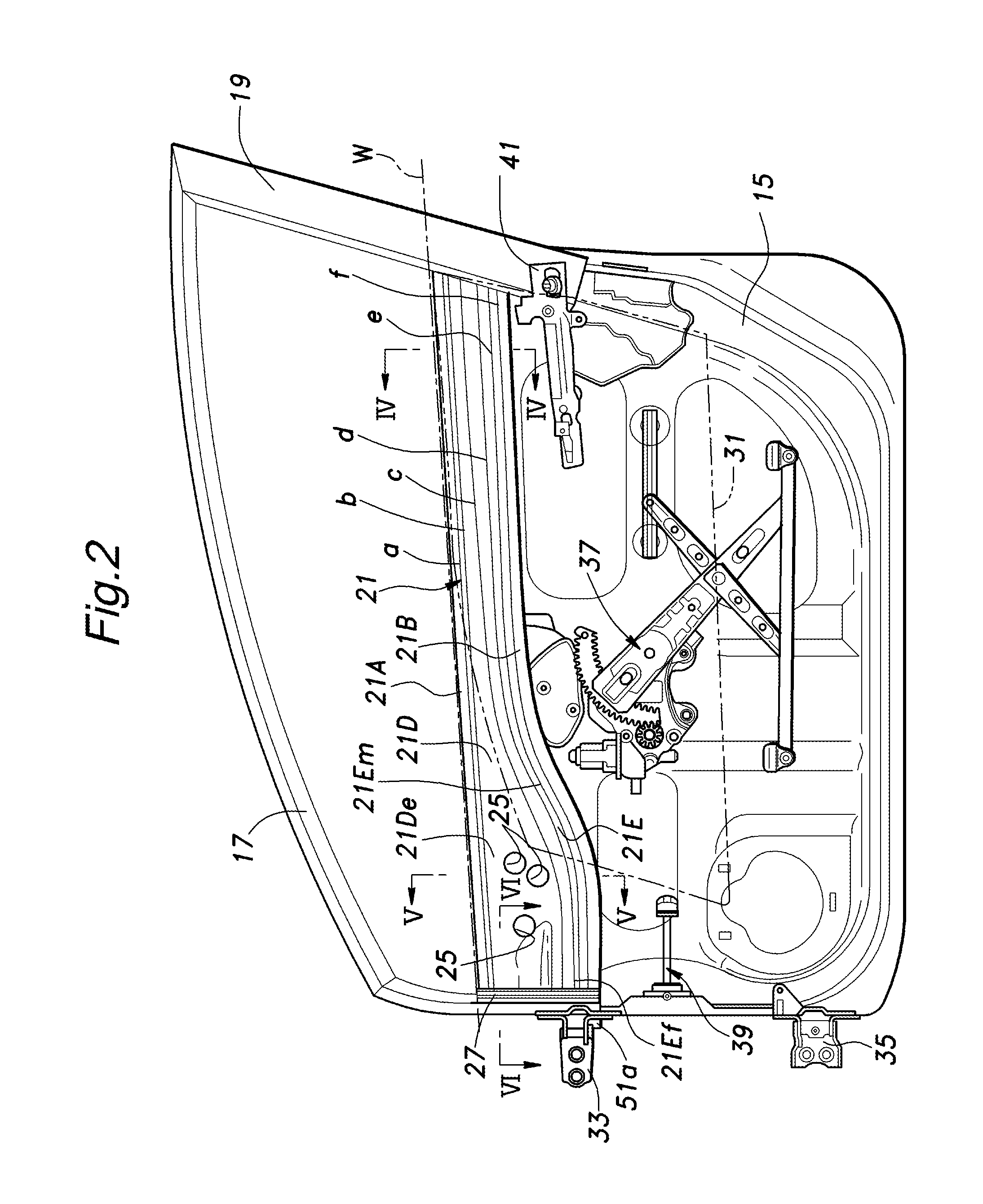
[0013]In particular, the convex side of the upper channel section may face outboard while the convex side of the lower channel section faces inboard, and a rear part of the lower channel section may be smoothly connected to a front part of the lower channel section via a vertically slanting section thereof. Thereby, as compared with the case where the lower channel section extends horizontally at the same elevation as the hinge, the internal space of the door that is required for receiving various component parts such as a window regulator can be maximized, and the freedom in the layout of component parts in the door can be increased.
[0014]According to a particularly preferred embodiment of the present invention, the upper channel section has a bottom wall which is vertically enlarged in a front part of the door structure, an access hole being passed through the enlarged bottom wall for providing an access to a skin mounted door mirror.
[0015]Furthermore, if an engagement portion is provided in a front end of the door structure at a part aligning with the beam member, and a corresponding engagement portion is provided in a front pillar opposing the front end of the door structure so as to restrict an outboard displacement of the door structure at the time of a frontal crash by cooperating with the engagement portion of the door structure, as the frontal crash load causes the engagement portion of the door structure to be brought into engagement with the corresponding engagement portion of the pillar on the side of the vehicle body at a part aligning with the beam member along the fore and aft direction, and this constrains the inner panel to the vehicle body pillar, the vehicle door structure (inner panel) and the vehicle body pillar are prevented from moving relative to each other at a part adjacent to the beam member at the time of a frontal crash. Thereby, the reinforcement beam is ensured to function as designed in a both efficient and effective manner.
[0016]According to a particularly preferred embodiment of the present invention, the engagement portion of the door structure comprises a projecting member, and the corresponding engagement portion of the front pillar comprises an opening configured to receive the projecting member. In this case, the projecting member may be provided on a part of the inner panel bent toward the front end of the door structure. If a nut member is attached to the bent part of the inner panel, and the projecting member comprises a head of a threaded bolt threaded into a threaded hole of the nut member, the assembly work can be simplified. To prevent the intrusion of foreign matters and moisture into the hole for receiving the projecting member, and the impairment of the external appearance, the vehicle door structure may further comprise a closure member that normally closes the opening, and drops off when the projecting member is received in the opening.

Problems solved by technology

The reinforcement beam for the side door, in particular the front side door is required to be able to transmit the frontal crash load from the front pillar to the center pillar in an appropriate manner, serves as a reaction force member for supporting a bending moment created around the connecting part between the lower end of the front pillar lower member and the front end of the side sill at the time of a frontal crash, absorbs the impact load at the time of a side crash by a collapsing deformation of the cross section thereof, and does not prevent the placement of various components within the internal space of the door such as a window regulator.
Even when a reinforcement beam is incorporated in the side door, if the side door and the front pillar deform laterally as a result of a rearward deformation of the front pillar due to a frontal crash load, the reinforcement beam may be unable to effectively perform its function, and fully serve as a load path member for transmitting a frontal crash load from the front pillar to the center pillar.

Method used


Image

  • Vehicle door structure
  • Vehicle door structure
  • Vehicle door structure

Examples


Embodiment Construction

)

[0027]An embodiment of the vehicle door structure of the present invention will now be described in the following with reference to FIGS. 1 to 6.

[0028]FIG. 1 is a view of a motor vehicle incorporated with a vehicle door structure embodying the present invention. In FIG. 1, numeral 1 denotes a vehicle body 1, numeral 3 denotes front wheels, numeral 5 denote rear wheels, numeral 7 denotes front side doors 7, numeral 9 denotes rear side doors 9, and numeral 11 denotes a tailgate.

[0029]The vehicle door structure of the present invention is applied to the front side door 7 in the illustrated embodiment, but can be applied to either the front side door 7 or the rear side door 9.

[0030]A shown in FIGS. 2-6, the front side door 7 comprises an outboard outer panel 13, an inboard inner panel 15, and a door sash 17 attached to an upper part of the inner panel 15 and defining a door window opening 19 jointly with the inner panel 15. The outer panel 13 and inner panel 15 are formed by stamp form...


PUM


Abstract

The frontal crash load is transmitted from a front pillar to a center pillar in a reliable manner so that a bending moment caused by the frontal crash load is favorably supported, and the deformation of the door is avoided. A beam member attached to an inner panel includes a S shaped cross section member. An upper channel section of the S shaped cross section member extends along the lower edge of a window opening, and a lower channel section extends adjacent to and in parallel to the lower edge of a window opening in a rear part of the door and is offset toward a lower part of the vehicle body in a rear part of the door, with a front end being located at a same elevation as an upper door hinge.

Description

TECHNICAL FIELD[0001]The present invention relates to a vehicle door structure, and in particular to a side door structure incorporated with a countermeasure against a frontal crash or a side crash event.PRIOR ART[0002]Typically, a vehicle door structure used as a side door comprises an outboard outer panel and an inboard inner panel. As reinforcement, the vehicle door structure is fitted with a reinforcement beam called as door beam having a front end attached to a front part of the inner panel, and a rear end connected to a rear part of the inner panel, and extending in the fore and aft direction of the vehicle body. Various forms of door beams have been proposed such as a steel channel member defining a box-shaped cross section jointly with the inner panel, a beam member having a dual-top hat shaped cross section, and a pipe member. See patent documents 1, 2 and 3.[0003]The door beam having any of the aforementioned cross sections can function as a load path member in the fore an...

Claims


Application Information

Patent Timeline
Patent Type & Authority Patents(United States)
IPC IPC(8): B60J5/06B60J7/00
CPCB60J5/0426B60J5/0443B60J5/0431B60J5/0444B60J5/0436B60J5/0458B60J5/0462
Inventor YASUHARA, SHIGETOSEGAWA, SHINGO
Owner HONDA MOTOR CO LTD
Why Eureka
Try Eureka