Steam engine

a steam engine and steam technology, applied in the field of steam engines, can solve the problems of adverse reduction of engine performance, and achieve the effect of high output and high efficiency

Inactive Publication Date: 2005-11-24
DENSO CORP
View PDF6 Cites 15 Cited by
  • Summary
  • Abstract
  • Description
  • Claims
  • Application Information

AI Technical Summary

Benefits of technology

[0008] The present invention is made in view of the above problems. It is an object of the present invention to provide a steam engine having a high output and high efficiency, in which mechanical energy is generated by heating and cooling down the working fluid filled into a fluid container, and the fluid pressure in the fluid container is prevented from exceeding the saturated vapor pressure during the operation.

Problems solved by technology

In such a case, the engine performance is adversely decreased.

Method used


Image

  • Steam engine
  • Steam engine
  • Steam engine

Examples


Embodiment Construction

[0024] An embodiment of the present invention will now be explained with reference to the drawings.

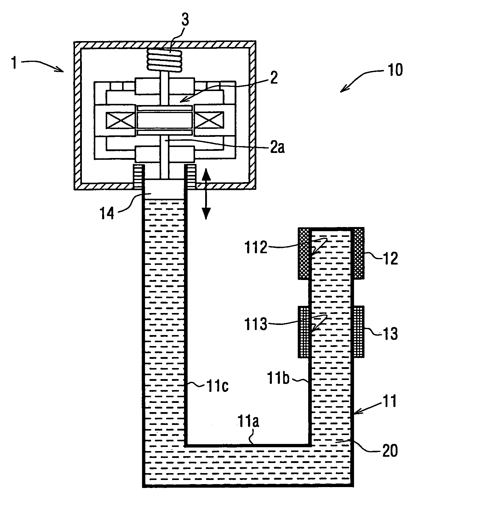
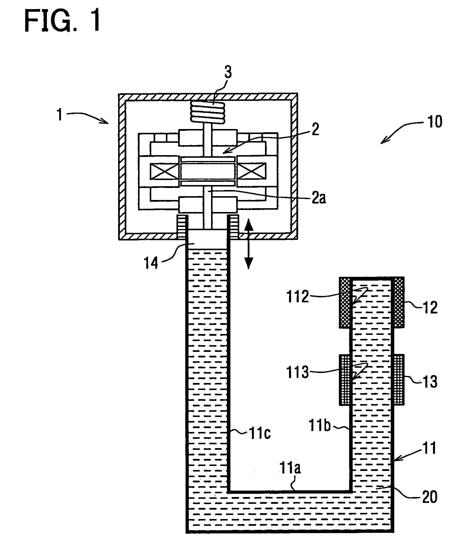
[0025] In FIG. 1, an electric power device comprises a steam engine 10 and an output device (an electric power generator) 1.

[0026] The steam engine 10 operates the electric power generator 1, so that electromotive force is generated by vibrating (oscillating) a moving member 2, to which a permanent magnet (not shown) is fixed.

[0027] As shown in FIG. 1, the steam engine 10 comprises a fluid container 11 in which working fluid 20 is filled, a heating device 12 provided at a heating portion 112 of the fluid container 11 and for heating the working fluid 20 in the fluid container 11, and a cooling device 13 provided at a cooling portion 113 of the fluid container 11 and for cooling down steam generated at the heating device 12.

[0028] The fluid container 11 is preferably made of such material having a high heat insulating characteristic, except for the heating portion 112 and the coolin...


PUM


Abstract

A steam engine has a pipe shaped fluid container, a heating and cooling devices respectively provided at a heating and cooling portions of the fluid container, and an output device connected to the fluid container, so that the output device is operated by the fluid pressure change in the fluid container, to generate an electric power. In such a steam engine, the fluid pressure in the fluid container is adjusted such that the fluid pressure does not exceed a saturated vapor pressure at the operating temperature. As a result, unnecessary condensation and liquefaction of the steam due to the increased pressure higher than the saturated vapor pressure can be prevented, to improve performance of the steam engine.

Description

CROSS REFERENCE TO RELATED APPLICATION [0001] This application is based on Japanese Patent Application No. 2004-150722, which is filed on May 20, 2004, the disclosure of which is incorporated herein by reference. FIELD OF THE INVENTION [0002] The present invention relates to a steam engine for converting heat energy into mechanical energy. BACKGROUND OF THE INVENTION [0003] An apparatus for a steam engine is known in the art, for example as disclosed in Japanese Patent Publication No. S58-057014. In the steam engine, working fluid is filled in a fluid container, the working fluid is heated and vaporized by a heating device, and the working fluid is cooled down and liquefied by a cooling device, so that fluid pressure in the fluid container is changed. A piston is displaced depending on such fluid pressure change, to obtain mechanical energy. [0004] It is necessary to increase temperature and pressure of steam to be generated in the fluid container by heating the working fluid, in or...

Claims


Application Information

Patent Timeline
Patent Type & Authority Applications(United States)
IPC IPC(8): F01B29/12A22C5/00F01K1/00F01K13/02F01K27/00
CPCF01K27/005
Inventor KOMAKI, KATSUYAODA, SHUZOOOCHI, TAKESHIYATSUZUKA, SHINICHI
Owner DENSO CORP
Why Eureka
Try Eureka