Optical displacement sensor and external force detecting device

Inactive Publication Date: 2005-11-24
MINEBEA CO LTD
View PDF8 Cites 10 Cited by
  • Summary
  • Abstract
  • Description
  • Claims
  • Application Information

AI Technical Summary

Benefits of technology

[0019] Thus, the optical displacement sensor according to the present invention uses only one light source together with three light receiving elements, and therefore can be downsized compared to a conventional optical displacement s

Problems solved by technology

However, since, as described above, in the conventional six-axis force sensor each of the three optical displacement sensors must be provided with a light source and also a light receiving element, the sizes of the light source and the ligh

Method used


Image

  • Optical displacement sensor and external force detecting device
  • Optical displacement sensor and external force detecting device
  • Optical displacement sensor and external force detecting device

Examples


Embodiment Construction

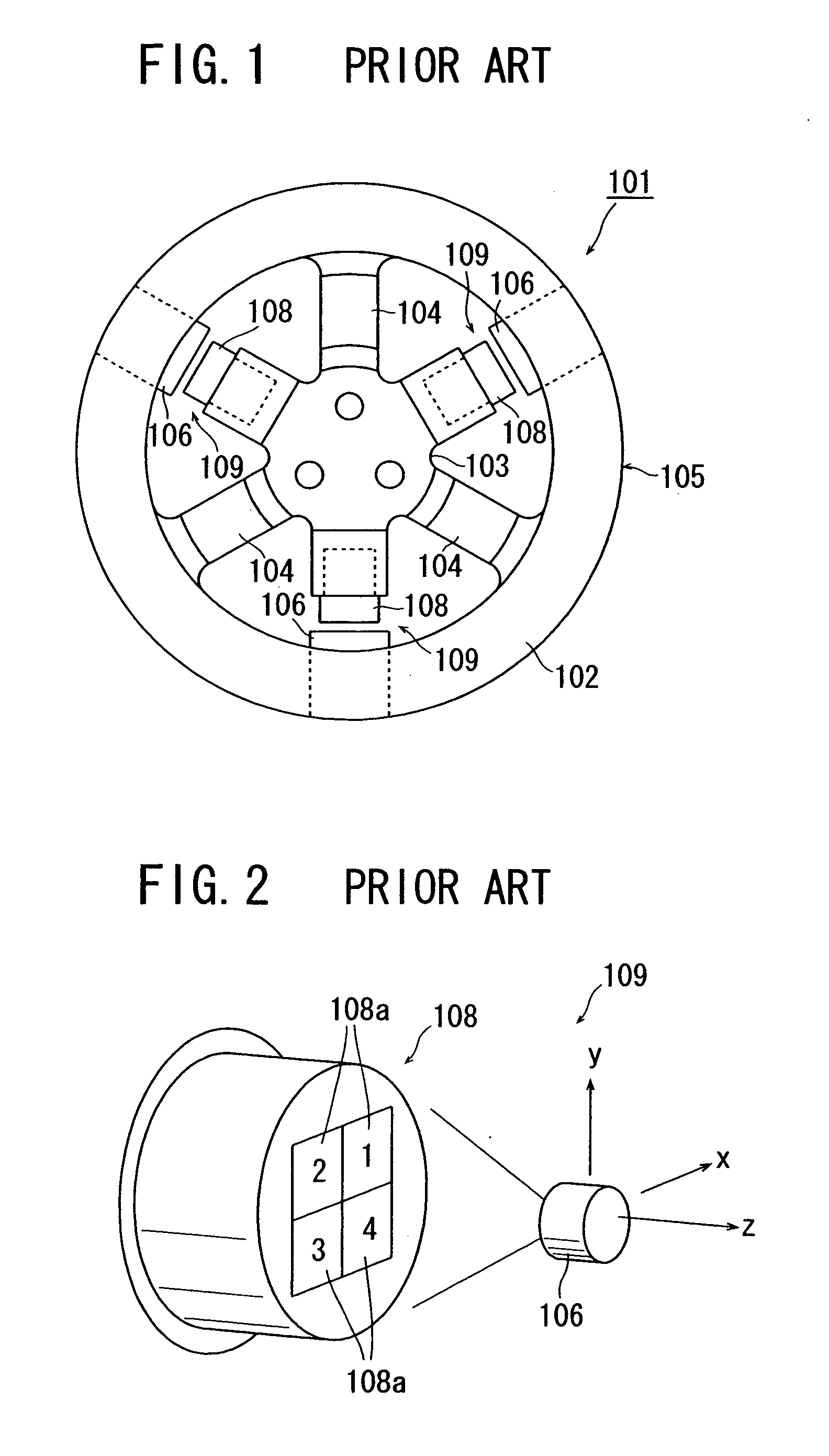
[0030] A preferred embodiment of the present invention will hereinafter be described with reference to the accompanying drawings. In the embodiment described below, an optical displacement sensor according to the present invention is applied to such a six-axis optical force sensor, for example, as shown in FIG. 1, but the present invention is not limited to application to an external force detecting device to detect six-axis force.

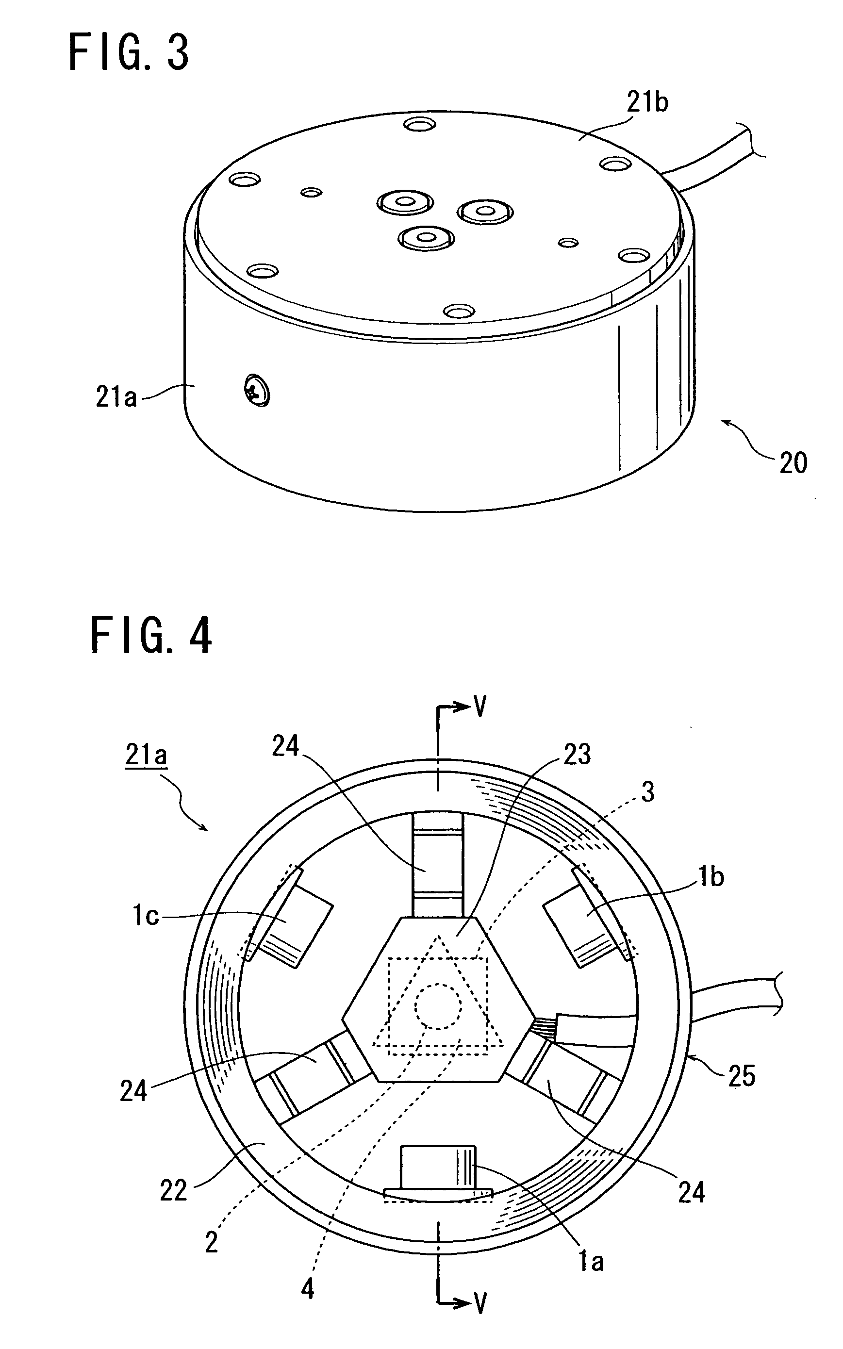
[0031] Referring to FIG. 3, a six-axis force sensor 20 according to the present invention comprises a main body 21a shaped cylindrical, and a top lid 21b shaped like a disk and disposed at the top of the main body 21a.

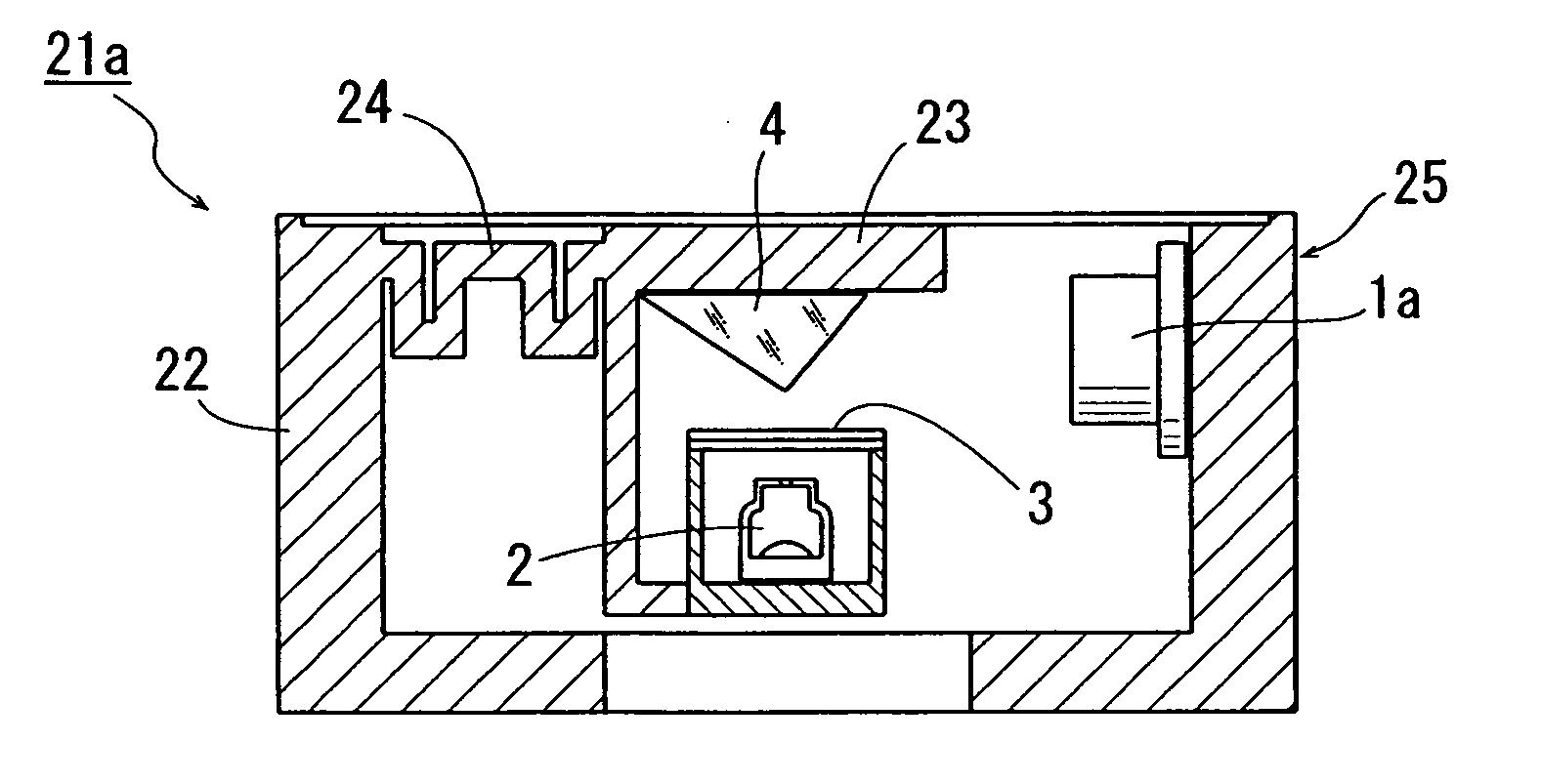
[0032] Referring then to FIGS. 3 and 4, the main body 21a of the six-axis force sensor 20 is constituted by a frame 25, which includes a support section 22 shaped into a hollow cylinder (circular cylinder in the figures, but may alternatively be a polygonal cylinder), an action section 23 disposed centrally inside the support section 22, an...


PUM


Abstract

An external force detecting device comprises a hollow-cylindrical support section, an action section disposed centrally inside the support section, and an optical displacement sensor which includes, at the action section on its center axis: a light source to emit a light beam in a direction along the center axis of the action section; a light branching member to branch the light beam into three light beams to progress respectively in three directions oriented at an equi-angular distance; and a light reflecting member to reflect the three light beams in a direction parallel to a plane perpendicular to the center axis, and which also includes, at the support section, three light receiving elements arranged in a rotation-symmetric manner at a 120 degree interval with their light receiving faces looking toward the center axis of the action section so as to receive respectively the three light beams reflected.

Description

BACKGROUND OF THE INVENTION [0001] 1. Field of the Invention [0002] The present invention relates to an optical displacement sensor and an external force detecting device, and more particularly to an optical displacement sensor adapted to sense and detect a relative positional displacement between a reference object, namely a support section and a measurement object, namely an action section based on displacement of a light reception position, and further to an external force detecting device adapted to detect an external force applied to the measurement object, namely the action section based on an output signal from the optical displacement sensor. [0003] 2. Description of the Related Art [0004] An external force detecting device, such as a six-axis optical force sensor, is conventionally known, in which a displacement amount of an action section (measurement object) to receive an external force relative to a support section (reference object) to support the action section is dete...

Claims


Application Information

Patent Timeline
IPC IPC(8): G01L1/04G01B11/00G01L5/16G02B6/38
CPCG01L5/166
Inventor KITAMURA, ATSUSHIADACHI, SHIGEYUKITANABE, SAWA
Owner MINEBEA CO LTD
Why Eureka
Try Eureka