Sliding device

a sliding device and a technology of sliding device, which are applied in the direction of linear bearings, mechanical devices, gearing, etc., can solve the problems of not being able to meet the requirements of the site in height dimension, the construction of sliding devices of the type, and the inability to meet the requirements of the site in height, etc., to achieve easy construction, reduce the overall height, and reduce the effect of overall heigh

Active Publication Date: 2005-11-24
NIPPON THOMPSON
View PDF11 Cites 17 Cited by
  • Summary
  • Abstract
  • Description
  • Claims
  • Application Information

AI Technical Summary

Benefits of technology

[0007] The present invention, therefore, has as its principal object to overcome the problems stated earlier and, in particular, to provide a sliding device that is extensively acceptable for standard specifications and has a sliding unit composed of a guide rail and a slider traveling relatively to the guide rail, and a lead screw lying out of the guide rail in a way extending by the side of and in parallel with the guide rail, as opposed to the prior sliding device disclosed in the commonly owned the Japanese Patent Laid-Open No. H11-30234. The major concept of the present invention is to provide the sliding device that is made reduced in the overall height as compared with the same sort of the prior sliding device. Another concept of the present invention is to provide a sliding device in which the lead screw may be easily made varied depending on design considerations with no need of altering the specifications of the associated linear motion guide unit and also mounted and demounted from the linear motion guide unit. Making the sliding device as small as possible in overall height is convenient for the installation in the site constrained in height dimension, and ready to customize the device in compliance with user's application and usage, even with simple construction as well as inexpensive cost.
[0014] The sliding device constructed as stated earlier is remarkably reduced in the overall height, compared with the sliding device disclosed in the commonly owned Japanese Patent Laid-Open No. H11-30234. Especially, the sliding device of the present invention is beneficial to make the sliding device compact in construction of the type having the guide rail that is made of a pair of side walls interconnected with one another. With the sliding device constructed as stated earlier, the ball nut mating with the lead screw to move for reciprocation the slide table along the guide rail is mounted detachably to the slide table while the lead screw is carried at the axial opposing ends thereof on the bracket bearings that are fastened on the top surfaces of the guide rail. Just exchanging the lead screw in the ball-nut screw system is sufficient to cope with maintenance of the sliding device and various design versions including altering the guide rail in length, the lead screw in lead or diameter, and the like. Thus, the sliding device of the present invention may be made easier in disassembling / reassembling works, and further made readily in various operations to mount the bracket bearings on the guide rail.

Problems solved by technology

Thus, the prior sliding device could not be availed in the site constrained in height dimension.
This means that the prior sliding devices of the type constructed as stated earlier are not ready for the appliance less in the overall height.
The prior actuator made therein with the window for the return tube as well as the U-shape recess for the ball-nut screw unit, however, would be inconvenient for the ball-nut screw units, which are different in design specifications.
Moreover, the slider, as much material being removed to make the recess and window, would get less in mechanical stiffness, unavailable for the appliances large in load capacity.

Method used


Image

  • Sliding device
  • Sliding device
  • Sliding device

Examples


Embodiment Construction

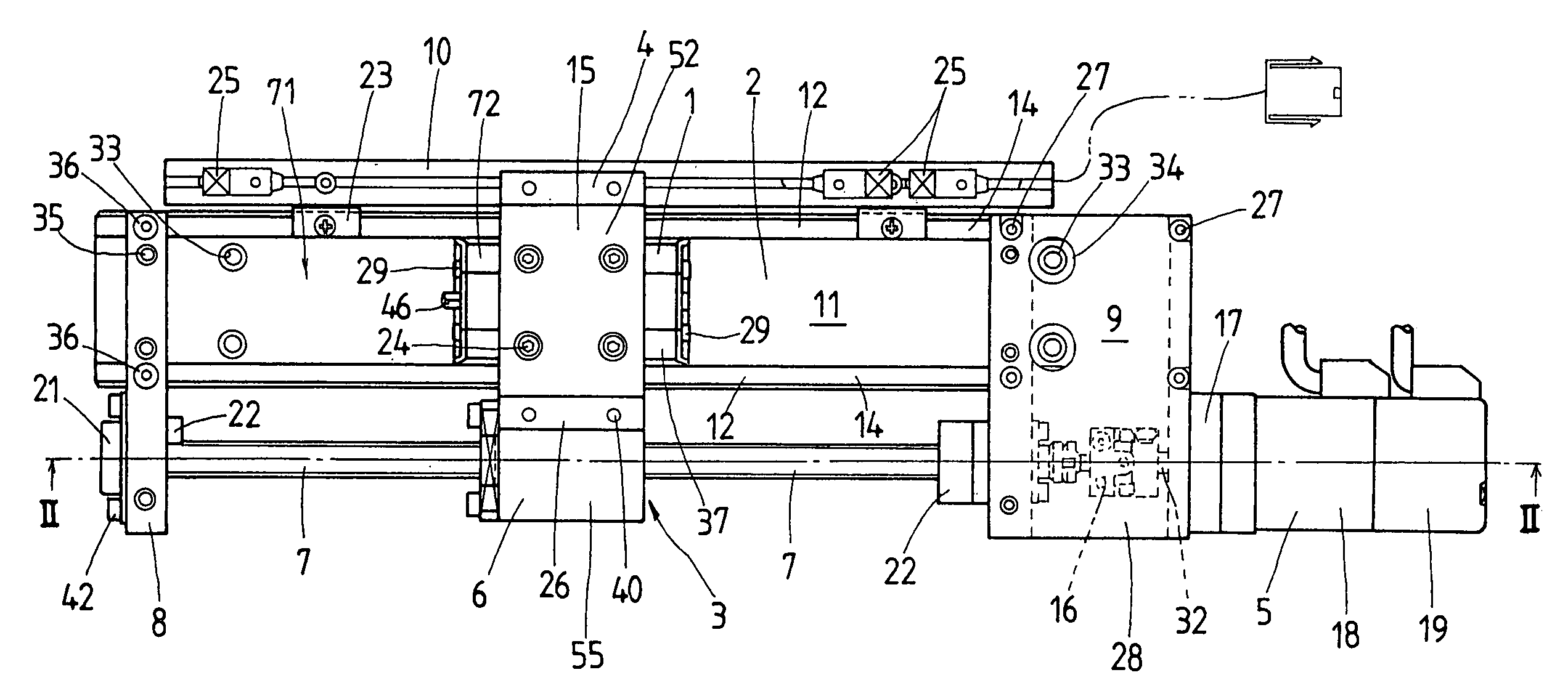
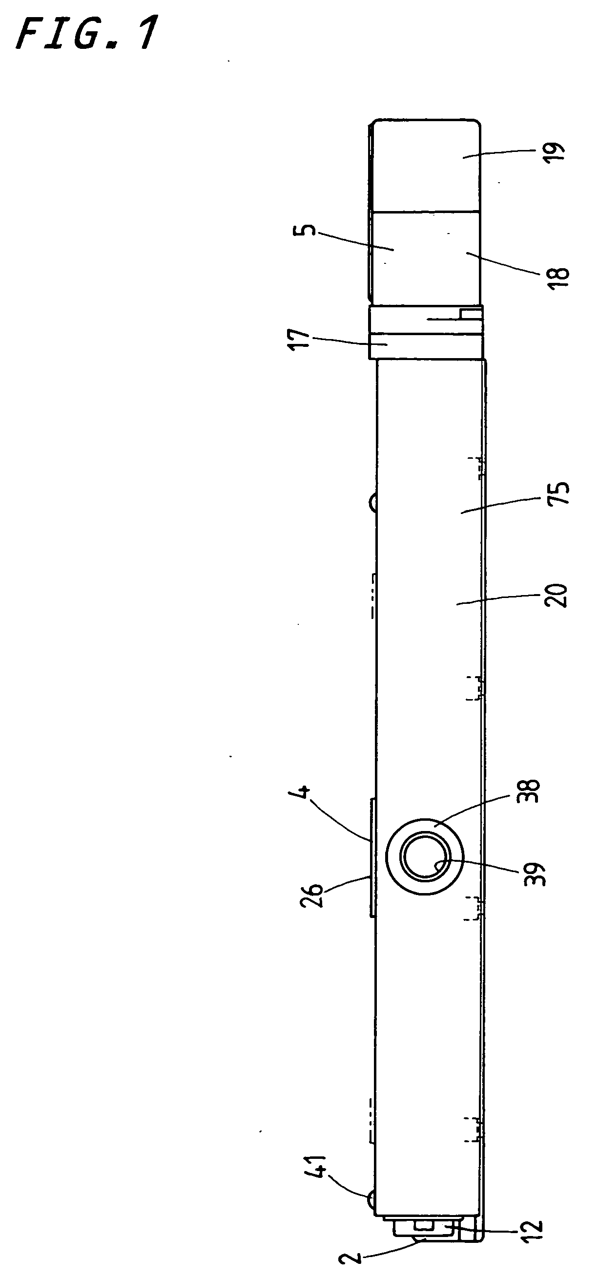
[0036] Referring now in detail to the accompanying drawings, a preferred embodiment of a sliding device according to the present invention will be explained below. The sliding device of the present invention will be well used in a diversity of machinery including semiconductor manufacturing apparatus, machine tools, various assembling apparatus, precision testing / measuring instruments, position control tables, sliding tables and so on, which have relatively sliding members that are not only needed to work in any controlled atmosphere including clean rooms, laboratories and the like, but also expected to in reverse work in an environment contaminated with dust and dirt.

[0037] A constructional features of the sliding device of the present invention, as seen in FIGS. 8 and 9, are well availed in the linear motion guide unit comprised of a guide rail and a slider as disclosed in the commonly owned Japanese Patent Laid-Open No. 2001-12465. The sliding device discussed later, besides the...


PUM

PropertyMeasurementUnit
lengthaaaaaaaaaa
diameteraaaaaaaaaa
heightaaaaaaaaaa

Abstract

A sliding device is provided in which a ball-nut screw system is disposed in a relation lying out of a guide rail and extending by the side of and in parallel juxtaposition with the guide rail, thereby making it possible to reduce the sliding device in the overall height. The ball-nut lead screw system may be easily mounted and / or demounted from the sliding device and easily made varied depending on design considerations. The sliding device includes the lead screw carried for rotation by bracket bearings in a way lying out of a guide rail in a way extending by the side of and in parallel juxtaposition with the guide rail, and a ball nut mounted to a slide table. The lead screw is actuated by a motor carried in a bracket bearing.

Description

FIELD OF THE INVENTION [0001] The present invention relates to a sliding device adapted for the use in a variety of machinery including machine tools, semiconductor manufacturing equipments, various assembling machines, testing instruments, and so on. BACKGROUND OF THE INVENTION [0002] Recent sliding devices have been needed to meet anticipated design specifications in extensively increased fields as diverse as machine tools, semiconductor manufacturing equipments, various assembling machines, testing instruments, and so on. An example of the sliding device compact or slim in construction is disclosed in, for example the Japanese Patent Laid-Open No. H11-30234 in which a guide rail is made of a pair of lengthwise sides joined together with one another while a lengthwise lead screw is carried at forward and aft ends thereof with bearing blocks that are rested above the guide rail. A slider is detachably connected with a ball nut mating with the lead screw to move on the guide rail in...

Claims


Application Information

Patent Timeline
Patent Type & Authority Applications(United States)
IPC IPC(8): F16H25/20F16H3/06F16H25/22F16H25/24
CPCF16H25/20F16H25/2204Y10T74/18656F16H2025/204Y10T74/18648F16H2025/2034F16C29/063F16C2322/39
Inventor YAMAGISHI, KAZUKI
Owner NIPPON THOMPSON
Why Eureka
Try Eureka