Motor housing and assembly process for impact wrench

a technology of impact wrenches and motor housings, which is applied in the field of power tools, can solve the problems of degrading the ability of the motor to move air through the motor for cooling, time-consuming operation, etc., and achieves the effect of simplifying the overall assembly simplifying the wire-up of the power tool, and improving the ability of the motor fan to move air through the motor

Active Publication Date: 2005-11-24
BLACK & DECKER INC
View PDF15 Cites 48 Cited by
  • Summary
  • Abstract
  • Description
  • Claims
  • Application Information

AI Technical Summary

Benefits of technology

[0004] Accordingly, a power tool overcoming the above-mentioned drawbacks is provided herein. The power tool includes a housing including a field case and front handle portion formed as a single piece, the front handle portion has an opening in a rear side thereof with a rear handle portion attached to the first handle portion for covering the opening. An end cap is connected to a first end of the field case. A motor is disposed in the field case which defines a generally cylindrical motor chamber. A trigger switch is disposed on the front handle portion and an electrical wire system including a plurality of wires is connected to the motor through the first end of the field case. The wires extend along an outer side surface of the field case and along the rear opening in the front handle portion. The wires are covered by the end cap and second handle portion of the housing. With the system of the present invention, the front handle design simplifies the wire-up of the power tool as well as simplifying the overall assembly of the power tool. In particular, all of the wire-up occurs on the rear side of the tool with no need to flip the tool over to complete the wire-up assembly. Also, the wires are along the outside of the housing, which allows the opening between the handle portion and motor portion of the housing to be removed. This improves the motor fan's ability to move air through the motor, by eliminating the air circulating in the handle portion.

Problems solved by technology

A common problem with power tools, particularly portable power tools of the mid-handle configuration having a “jam-pot” construction, concerns the ability with which a power tool so constructed may be assembled.
An often and time-consuming operation in this process concerns the connection of the wires from a power source such as a cord or a battery pack to the trigger switch and motor assembly.
This opening causes the motor fan to circulate some air in the handle portion, which degrades its ability to move air through the motor for cooling.

Method used


Image

  • Motor housing and assembly process for impact wrench
  • Motor housing and assembly process for impact wrench
  • Motor housing and assembly process for impact wrench

Examples


Embodiment Construction

[0016] The following description of the preferred embodiment(s) is merely exemplary in nature and is in no way intended to limit the invention, its application, or uses.

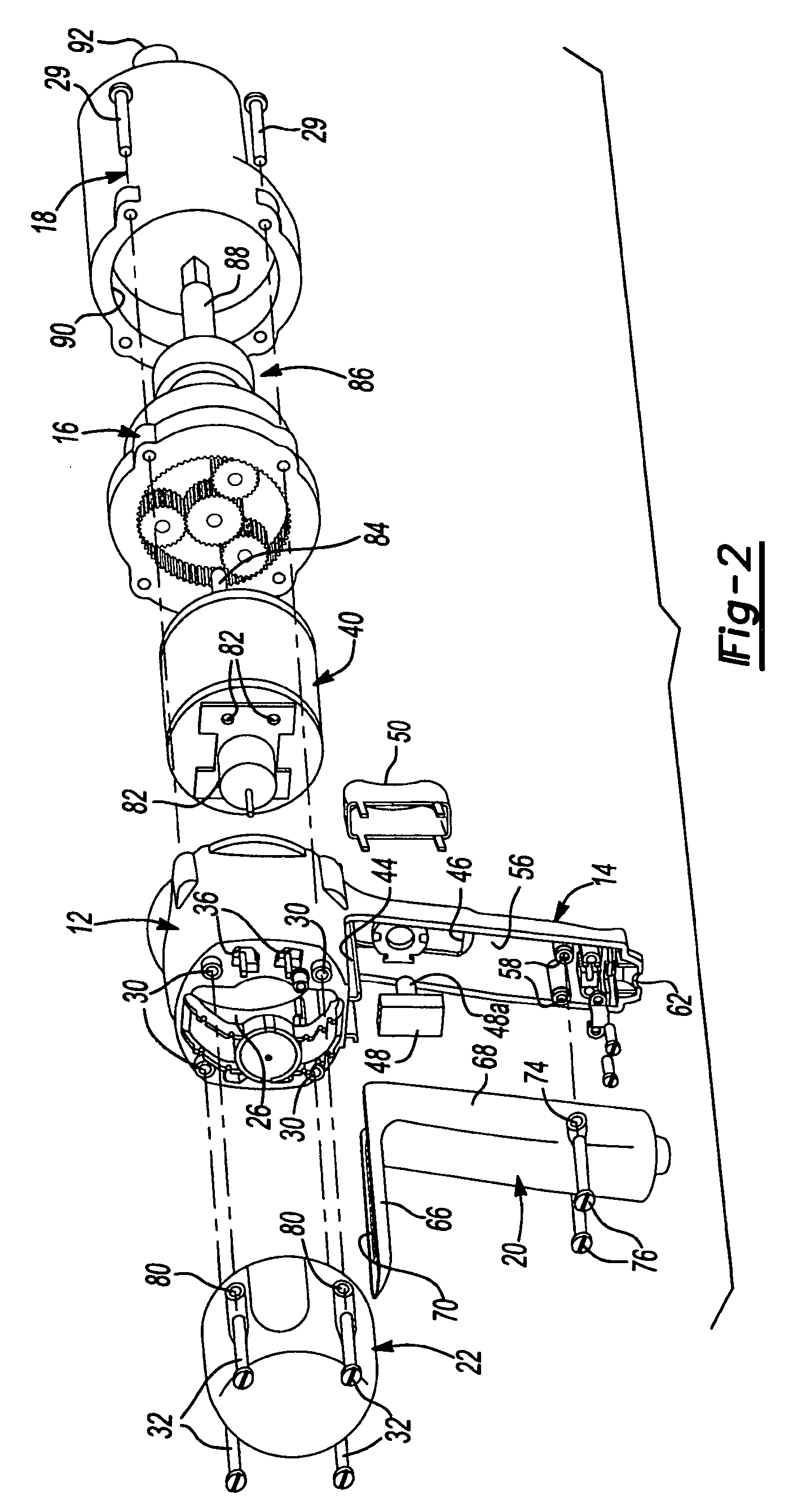
[0017] With reference to FIGS. 1-9, the power tool assembly according to the principles of the present invention will now be described. It should be understood that although the power tool of the present invention is illustrated in the form of a impact wrench-type power tool, the present invention can also be used with other power tools such as drills, hammer mechanisms, and other mid-handle type power tools, corded and cordless.

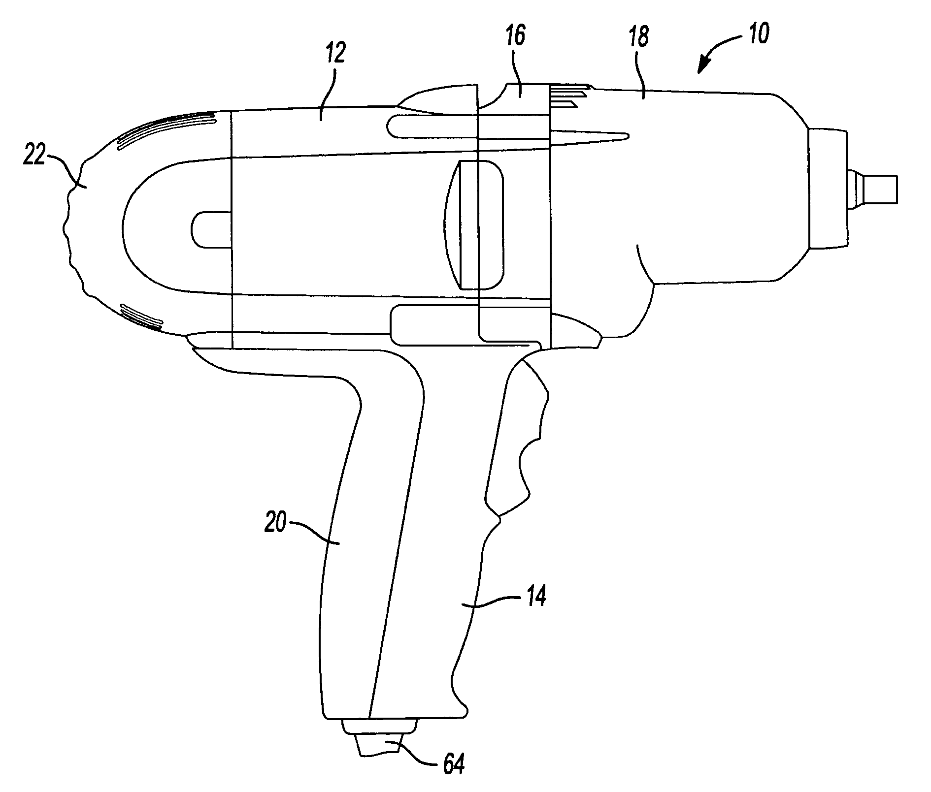
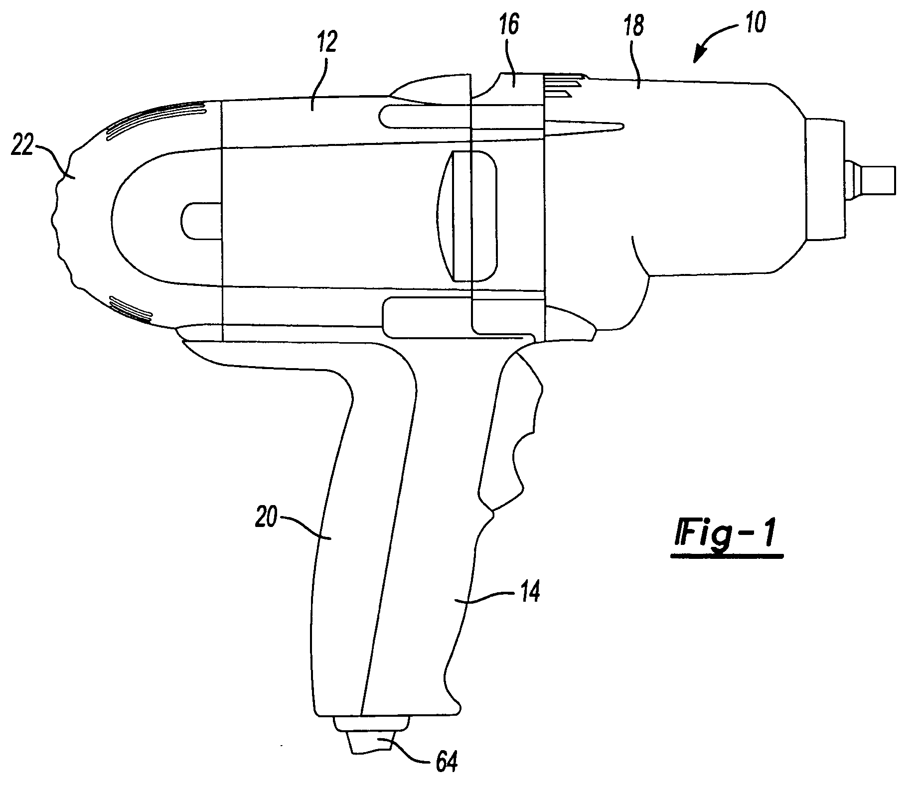
[0018] With reference to FIG. 1, power tool 10 is illustrated as including a field case 12 and front handle portion 14 formed as a unitary piece. A gear case cover 16 is mounted to a front of the field case 12 and a gear case 18 is mounted to the gear case cover 16. A rear handle portion 20 is mounted to the front handle portion 14 and an end cap 22 is mounted to a rear portion of the field...


PUM

PropertyMeasurementUnit
timeaaaaaaaaaa
areaaaaaaaaaaa
transition areaaaaaaaaaaa

Abstract

A handle for a power tool is provided including a field case and front handle portion formed as a single piece. The front handle portion has an opening in a rear side thereof for receiving the wiring for the power tool. The wiring is connected to a motor that is mounted in the field case. A rear handle portion is attached to the front handle portion for covering the opening in the rear of the front handle portion. An end cap is connected to a rear of the field case for covering the remaining exposed wires connected to the motor. With the front handle design, the wire-up of the power tool can be completed from one side of the tool without having to turn the tool over during the wire-up process.

Description

FIELD OF THE INVENTION [0001] The present invention relates to power tools, and more particularly, to a motor housing and assembly process for a power tool. BACKGROUND OF THE INVENTION [0002] A common problem with power tools, particularly portable power tools of the mid-handle configuration having a “jam-pot” construction, concerns the ability with which a power tool so constructed may be assembled. Typically, power tools having a jam-pot construction are assembled in a process wherein the subcomponents which form the wiring are initially installed into a first jam-pot opening and thereafter, the subcomponents are feed out through a second jam-pot opening. [0003] An often and time-consuming operation in this process concerns the connection of the wires from a power source such as a cord or a battery pack to the trigger switch and motor assembly. In a mid-handle tool, the connection of these wires can require that the tool be reoriented multiple times. The assembly operation is such...

Claims


Application Information

Patent Timeline
Patent Type & Authority Applications(United States)
IPC IPC(8): B25F5/02
CPCB25D2250/121Y10T29/49799B25F5/02
Inventor JUSTIS, MICHAEL S.BODINE, THOMAS J.PLATO, BARRY E.KUEHNE, BRENT A.
Owner BLACK & DECKER INC
Why Eureka
Try Eureka