
Cooperative traction control system

a traction control system and cooperative technology, applied in the direction of tractors, vehicle components, propulsion unit safety devices, etc., can solve the problems of limited ability of conventional tcs or vsa operations to respond to operation on low coefficient surfaces, limited effectiveness in terms of effectiveness, etc., to achieve low coefficient of friction and better handling and vehicle response

Inactive Publication Date: 2005-11-24
HONDA MOTOR CO LTD
View PDF11 Cites 14 Cited by
  • Summary
  • Abstract
  • Description
  • Claims
  • Application Information

AI Technical Summary

Benefits of technology

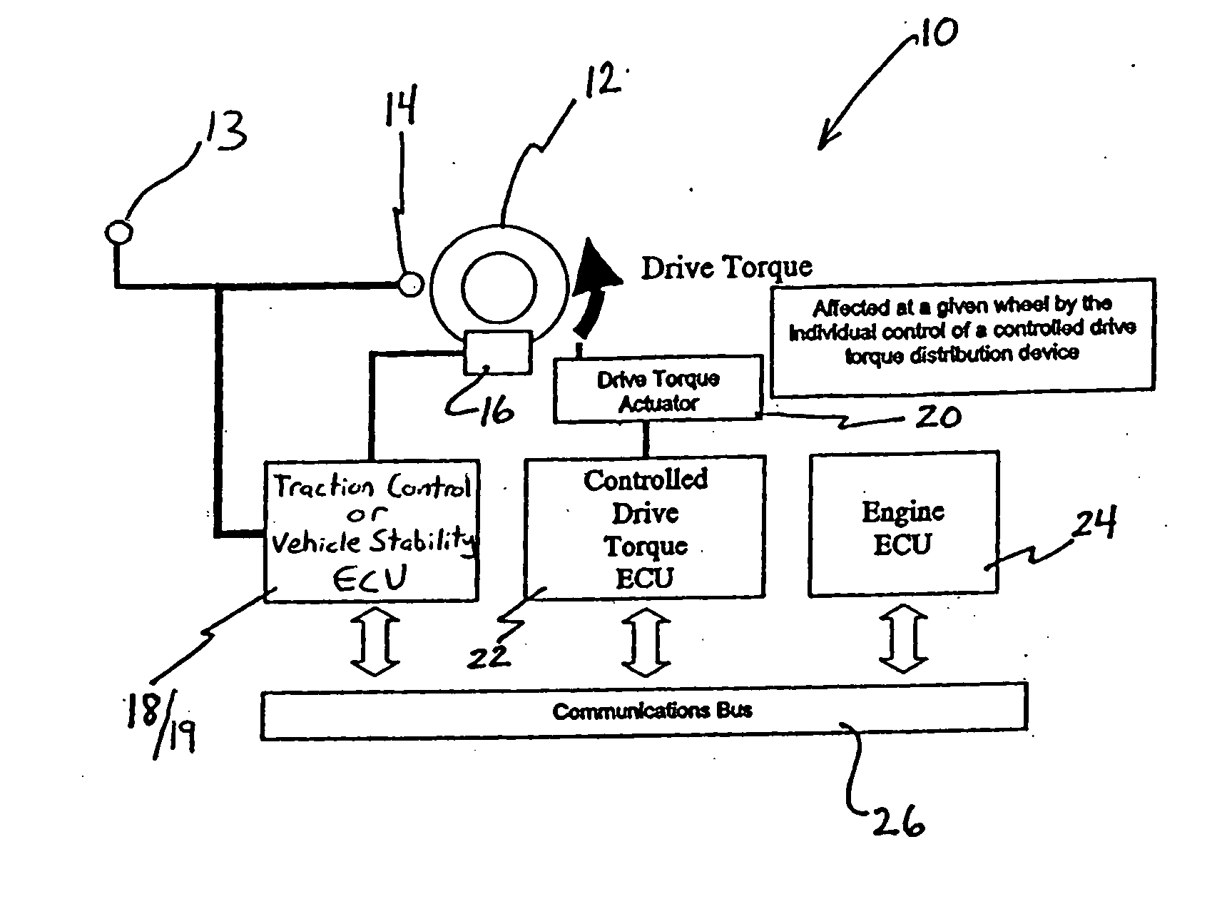
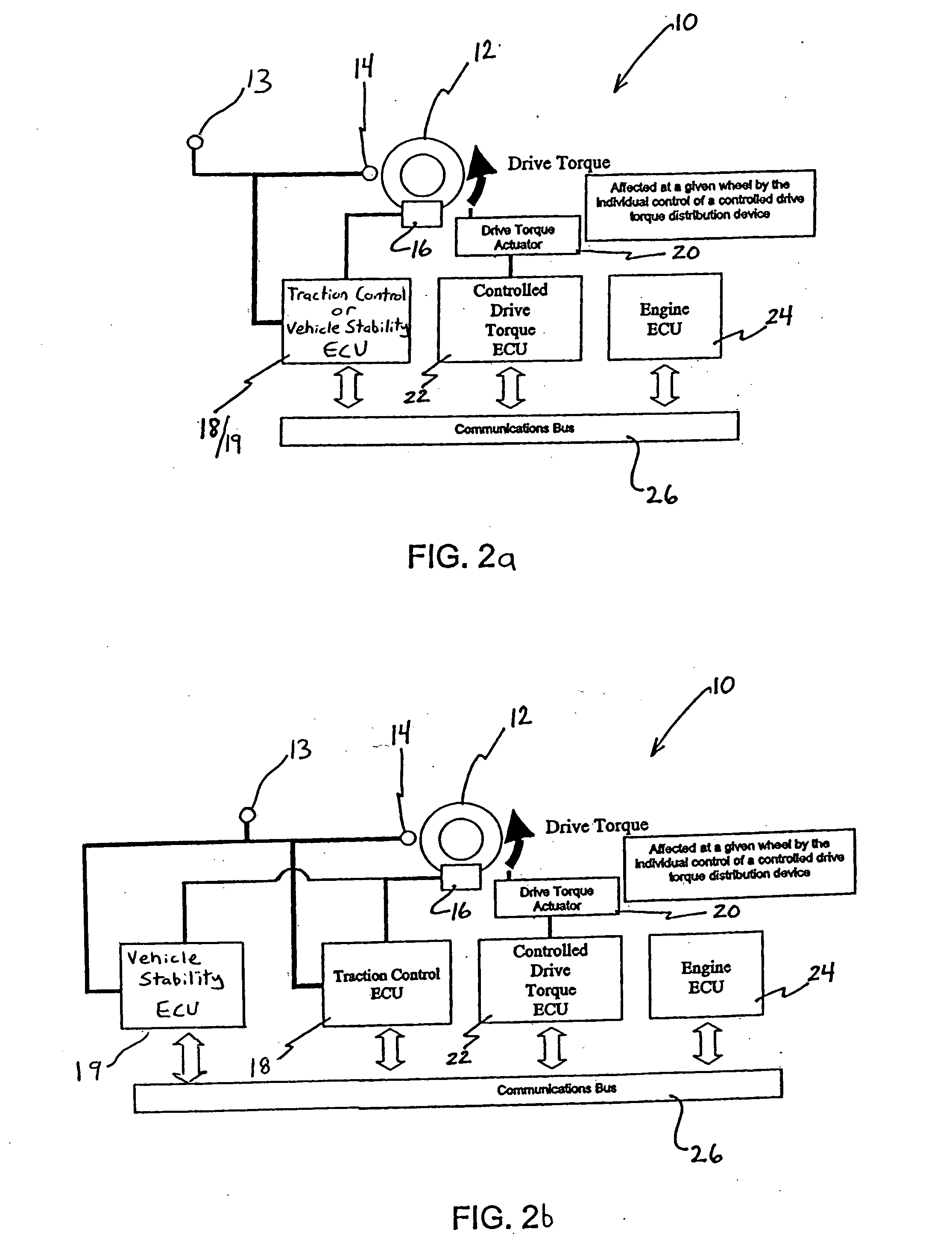
[0018] The present invention is directed toward a cooperative traction control system wherein the drive torque applied to the wheels is individually controlled or modulated to react to sensed wheel-slipping conditions and / or sensed wheel lateral skidding, so as to provide better handling and vehicle response, especially during low speed, tight-turn acceleration on surfaces having a relatively low coefficient of friction.

Problems solved by technology

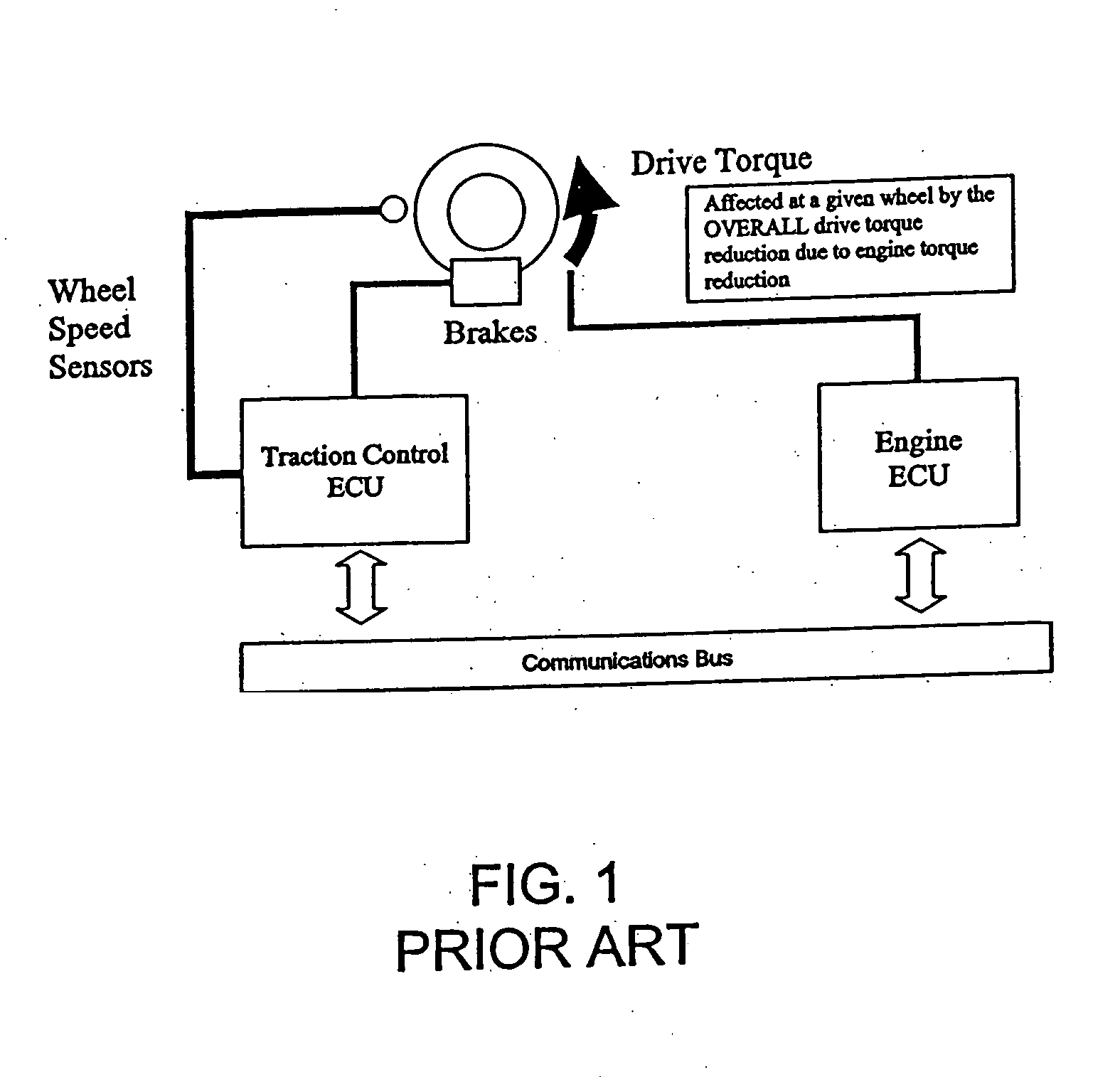
However, since the control of the total drive torque, as modulated by engine torque control, is not directly related to each wheel's drive torque condition (i.e. an engine torque change affects the overall torque but not specifically an individual wheel drive torque), it has limited effectiveness in terms of simultaneously keeping vehicle momentum and allowing a stable vehicle response while controlling wheel slip and / or lateral skid of an individual wheel.
However, it does not, in the current state of the art, have the capability to modulate individual tractive torques at each wheel through changes in drive torque distribution of the driveline.
It has been found that the conventional TCS or VSA operation has limited ability to respond to operation on low coefficient surfaces during turning and hard acceleration.
During vehicle launch on low coefficient surfaces and while turning in particular, there is a higher likelihood of loss of traction and potentially ensuing loss of yaw stability and / or vehicle maneuverability.
This usually results in a hesitation to the overall vehicle momentum because the amount of engine torque reduction required to reduce the most critical wheel slip and / or lateral skid also reduces the amount of tractive effort on other wheels that may not be in an excessive slip and / or lateral skid situation and may even have additional traction capability.
This hesitation may, in some cases, be detrimental and could lead to problems in some situations, such as hill climbing or operation in tightly confined spaces where acceleration is requested but not delivered due to this hesitation.

Method used


Image

  • Cooperative traction control system
  • Cooperative traction control system
  • Cooperative traction control system

Examples


first embodiment

[0047] With reference to FIG. 3, a flow chart illustrating a first preferred method of operating the cooperative traction control system 10 according to the present invention is provided. In this embodiment the cooperative traction control system provides a staged actuation of control systems to reduce wheel slip and / or lateral skid, as necessary.

[0048] In step 100, the wheels and vehicle motions are monitored and, in step 102, it is determined that a wheel is slipping and / or skidding laterally and / or the vehicle is progressing into or operating in a region of unstable motion. Thereafter, in step 104, the TCS ECU 18 and / or VSA ECU 19 communicates the necessary drive torque reduction amount to the drive torque ECU 22, which, in turn, activates the associated drive torque actuator 20 for the slipping and / or laterally skidding wheel to reduce the drive torque applied to the slipping and / or laterally skidding wheel. The slipping and / or lateral skidding condition of the wheels is sensed ...

second embodiment

[0054] With reference to FIGS. 6a and 6b, a cooperative traction control system 310 according to the present invention is illustrated. The cooperative traction control system 310 is installed on a vehicle having a plurality of wheels 312 and vehicle parameter sensors including wheel speed sensors 314, and / or vehicle motion sensors 313 (typically yaw rate, lateral g, longitudinal G, and steering angle). The cooperative traction control system 310 also includes brakes 316 associated with each wheel 312, a TCS ECU 318 and / or VSA ECU 319, a drive torque actuator 320 associated with each of the wheels 312, a drive torque ECU 322, an engine ECU 324, a communications bus 326, and a controllable suspension 317 that determines individual wheel loads.

[0055] The TCS ECU 318 and / or VSA ECU 319 is in communication with the brakes 316 of each wheel 312 (i.e., the brake actuators), and with the drive torque ECU 322 and the engine ECU 324 via the communications bus 326, as illustrated.

[0056] The T...


PUM


Abstract

A cooperative traction control system wherein individualized control over each wheel's longitudinal slip and/or lateral skidding is provided. The system uses a combination of an existing traction and stability module linked with a drive torque actuator capable of modulating the amount of drive torque at a given wheel on a specified axle. The system permits drive torque at the slipping and/or laterally skidding wheel to be controlled, either alone or in combination with brake actuation and throttle angle control, to reduce or control wheel slip and/or lateral skid and/or vehicle motion.

Description

[0001] This application is a continuation-in-part of prior U.S. application Ser. No. 10 / 983,393 filed on Nov. 8, 2004 which claims the benefit of currently pending U.S. Provisional Application 60 / 588,085 filed on Jul. 15, 2004. This application also claims the benefit of currently pending U.S. Provisional Application Ser. No. 60 / 572,732 filed on May 20, 2004 and currently pending U.S. Provisional Application 60 / 588,085 filed on Jul. 15, 2004; the entire disclosures of the preceding two provisional applications are incorporated by reference herein.BACKGROUND OF THE INVENTION [0002] 1. Field of the Invention [0003] The present invention is directed toward a methodology for independent longitudinal wheel slip and lateral skid control utilizing a traction control and a stability control system in cooperation with a drive torque distribution control system capable of individual wheel drive torque modulation. [0004] 2. Description of Related Art [0005] A vehicle system may consist of a va...

Claims


Application Information

Patent Timeline
Patent Type & Authority Applications(United States)
IPC IPC(8): B60K28/16B60T8/175B60T8/1755B60T8/18B60T8/48B60W10/06B60W10/18B60W30/02
CPCB60K28/16B60T8/175B60T8/1755B60W2520/26B60W10/06B60W10/184B60T8/4809
Inventor POST, JAMES W. IIKLAUS, THEODORE
Owner HONDA MOTOR CO LTD
Learn More