Position detector, camera-shake compensation mechanism, and image capture apparatus

a compensation mechanism and position detector technology, applied in the field of position detectors and camerashake compensation mechanisms, can solve the problems of difficult suppression of piece-to-piece variation influences, affecting the effect of image capture, and being susceptible to ambient temperature, so as to achieve the effect of easy compensating for influences

Inactive Publication Date: 2005-11-24
KONICA MINOLTA PHOTO IMAGING
View PDF3 Cites 43 Cited by
  • Summary
  • Abstract
  • Description
  • Claims
  • Application Information

AI Technical Summary

Benefits of technology

[0011] It is therefore an object of the present invention to provide a position detector capable of

Problems solved by technology

However, a Hall effect device and a magnet, characteristics of which are apt to greatly vary according to temperature, are susceptible to ambient temperature.
However, the technique suggested by JP No. 2001-91298 would have difficulties in suppressing influences of piece-to-piece variation.
More specifically, to merely obtain a quotient of output va

Method used


Image

  • Position detector, camera-shake compensation mechanism, and image capture apparatus
  • Position detector, camera-shake compensation mechanism, and image capture apparatus
  • Position detector, camera-shake compensation mechanism, and image capture apparatus

Examples


Embodiment Construction

[0037] Below, preferred embodiments of the present invention will be described with reference to accompanying drawings.

A. First Preferred Embodiment

[0038] Overview of Structure

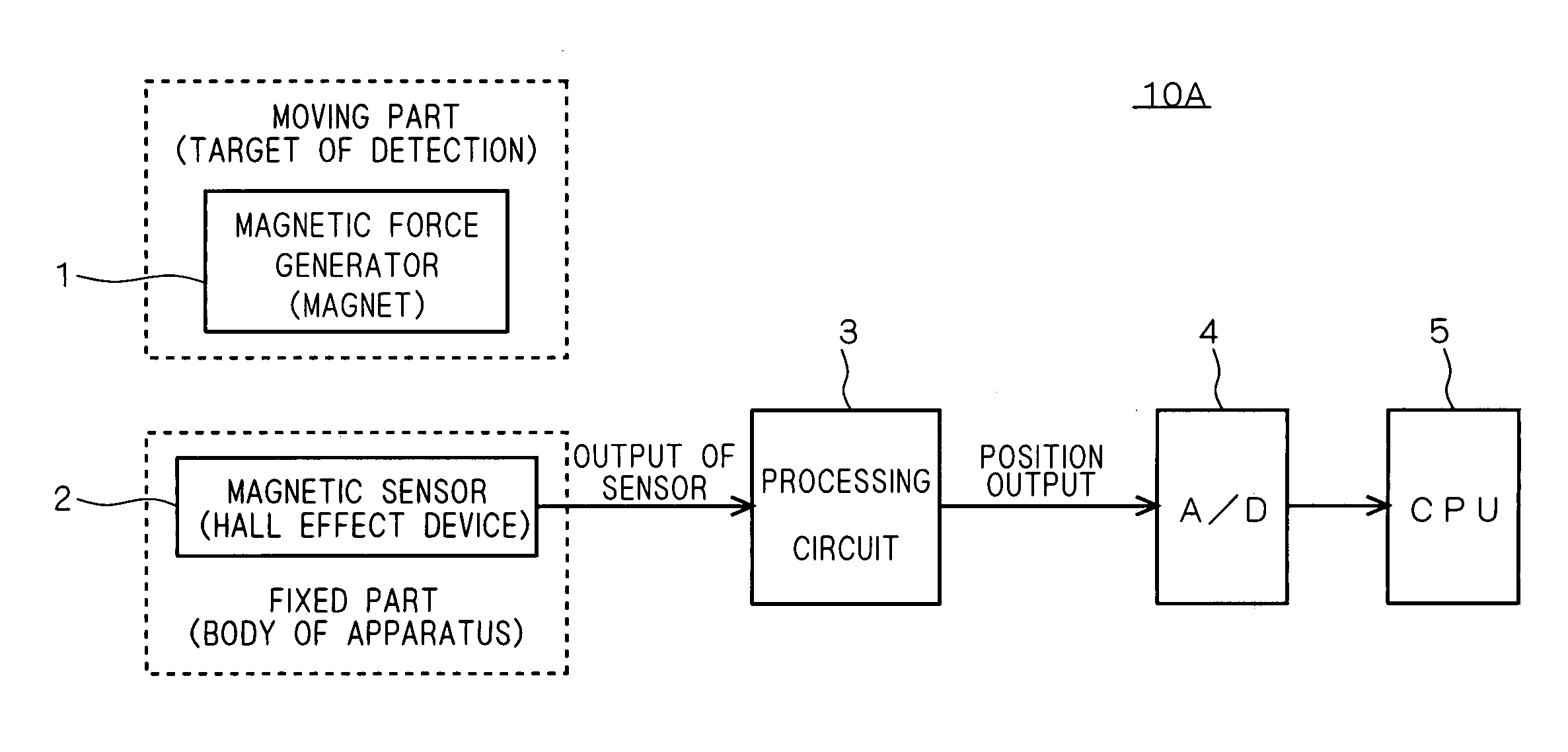
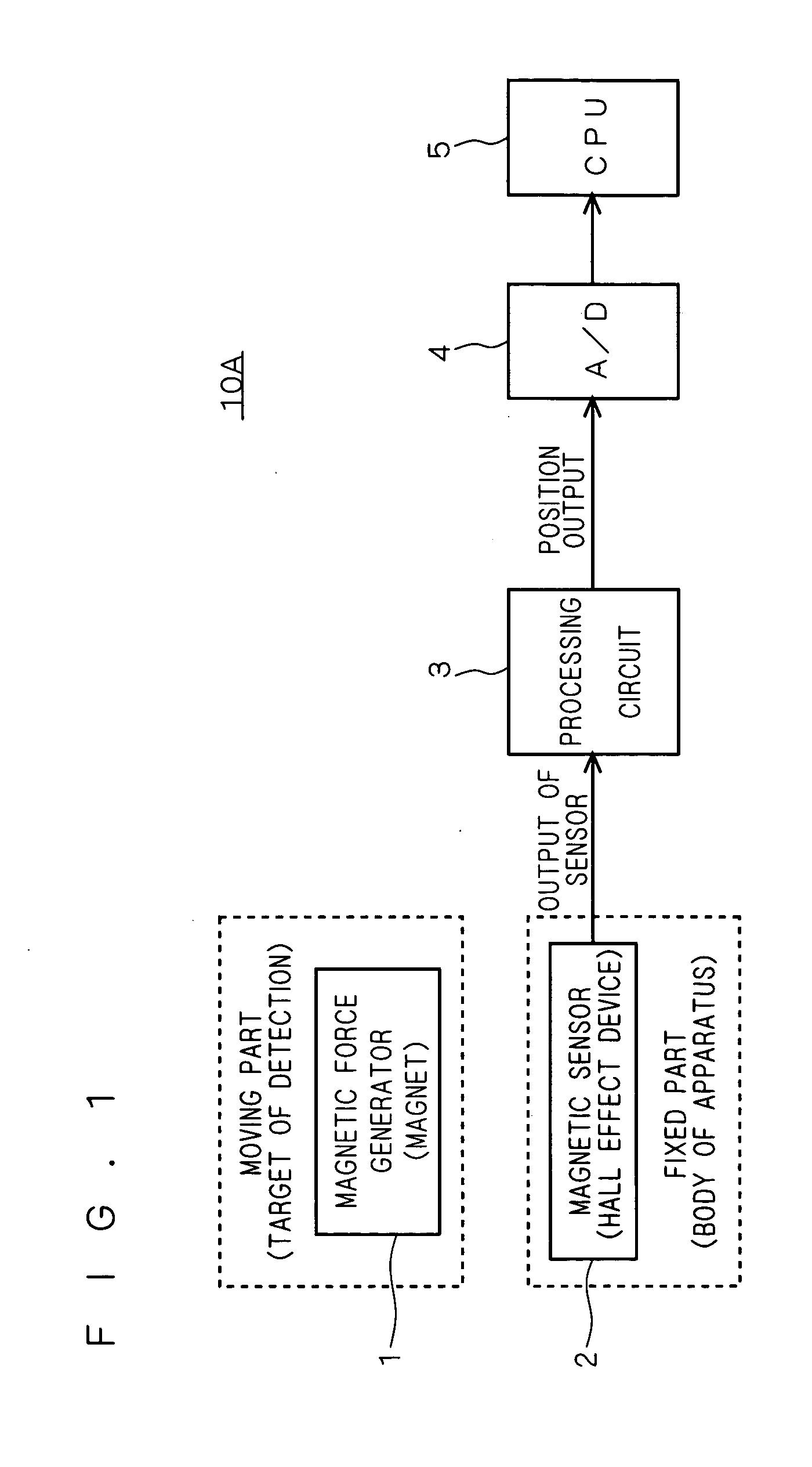
[0039] In a first preferred embodiment, description will be given by taking a position detector 10A for achieving one-dimensional position detection, as an example. The position detector 10A is a linear encoder of a magnetic type.

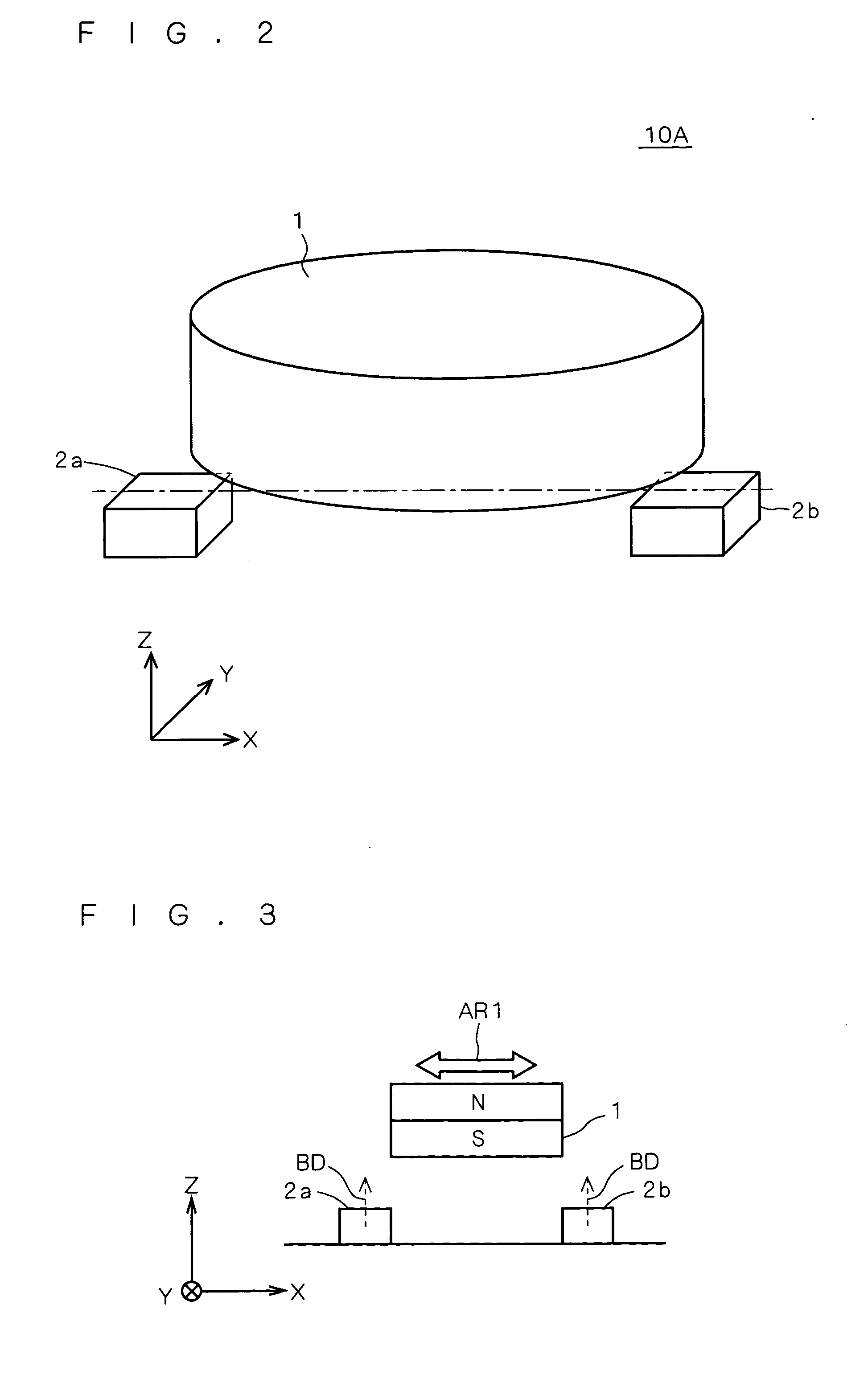
[0040]FIG. 1 schematically illustrates the position detector 10A. FIGS. 2 and 3 are a perspective view and a sectional view, respectively, both of which illustrate physical configuration of parts forming the position detector 10A. FIG. 4 illustrates an electrical processing circuit of the position detector 10A. Further, FIG. 5 shows a principle of position detection performed by a Hall effect device (magnetic sensor). It is additionally noted that though FIG. 1 illustrates a Hall effect device 2 as one unit for purposes of simplification, actually, a plurality of Hall effect devic...


PUM


Abstract

A position detector includes a magnet, a pair of Hall effect devices, and a processing circuit for detecting relative positions of the magnet and the pair of Hall effect devices. The processing circuit detects a difference in magnitude between output values of the Hall effect devices, as position outputs, with an input value to each of the Hall effect devices being controlled such that a sum of magnitudes of respective output values of the Hall effect devices is constant.

Description

[0001] This application is based on application No. 2004-150705 filed in Japan, the contents of which are hereby incorporated by reference. BACKGROUND OF THE INVENTION [0002] 1. Field of the Invention [0003] The present invention relates to a position detector for detecting relative positions of two objects, and a camera-shake compensation mechanism and an image capture apparatus each of which utilizes the position detector. [0004] 2. Description of the Background Art [0005] There are various types of position detectors for detecting relative positions of two objects (a linear encoder, for example). [0006] In order to meet demands for smaller size, lower cost, lower power consumption and the like, it is preferable to employ a position detector of a magnetic type which uses a permanent magnet (a magnetic force generator) and a Hall effect device (a magnetic sensor), among the various types of position detectors. [0007] However, a Hall effect device and a magnet, characteristics of wh...

Claims


Application Information

Patent Timeline
IPC IPC(8): G01B7/14G01D5/14G02B7/08G03B5/00G03B17/02H04N5/232
CPCG01D5/145H04N5/23287H04N5/23248G03B17/02H04N23/68H04N23/687
Inventor MASUDA, SATOSHIHARA, YOSHIHIRO
Owner KONICA MINOLTA PHOTO IMAGING
Why Eureka
Try Eureka