Freely deflecting knee probe with controlled scrub motion

Active Publication Date: 2005-11-24
MICRO PROBE
View PDF4 Cites 25 Cited by
  • Summary
  • Abstract
  • Description
  • Claims
  • Application Information

AI Technical Summary

Benefits of technology

[0007] The probes may be arrayed with tight pitch that is less than the total width of the probe. Adjacent suspension knees may overlap while leaving sufficient clearance. The probes may be assembled via their columnar structures for example in a sandwiching fixture and clamping plates that provide a shearing clamping of the columnar structures. The pro

Problems solved by technology

As size and pitch of test contacts decrease, it becomes increasingly difficult to tune the scrub motion irrespective of friction influences in the tip/contact interface.
It is n

Method used


Image

  • Freely deflecting knee probe with controlled scrub motion
  • Freely deflecting knee probe with controlled scrub motion
  • Freely deflecting knee probe with controlled scrub motion

Examples


Embodiment Construction

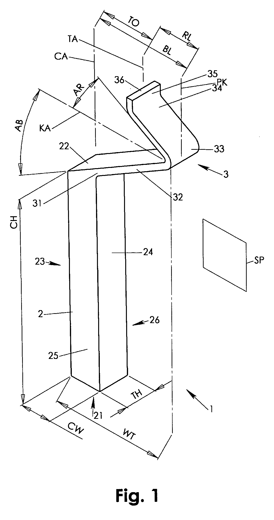
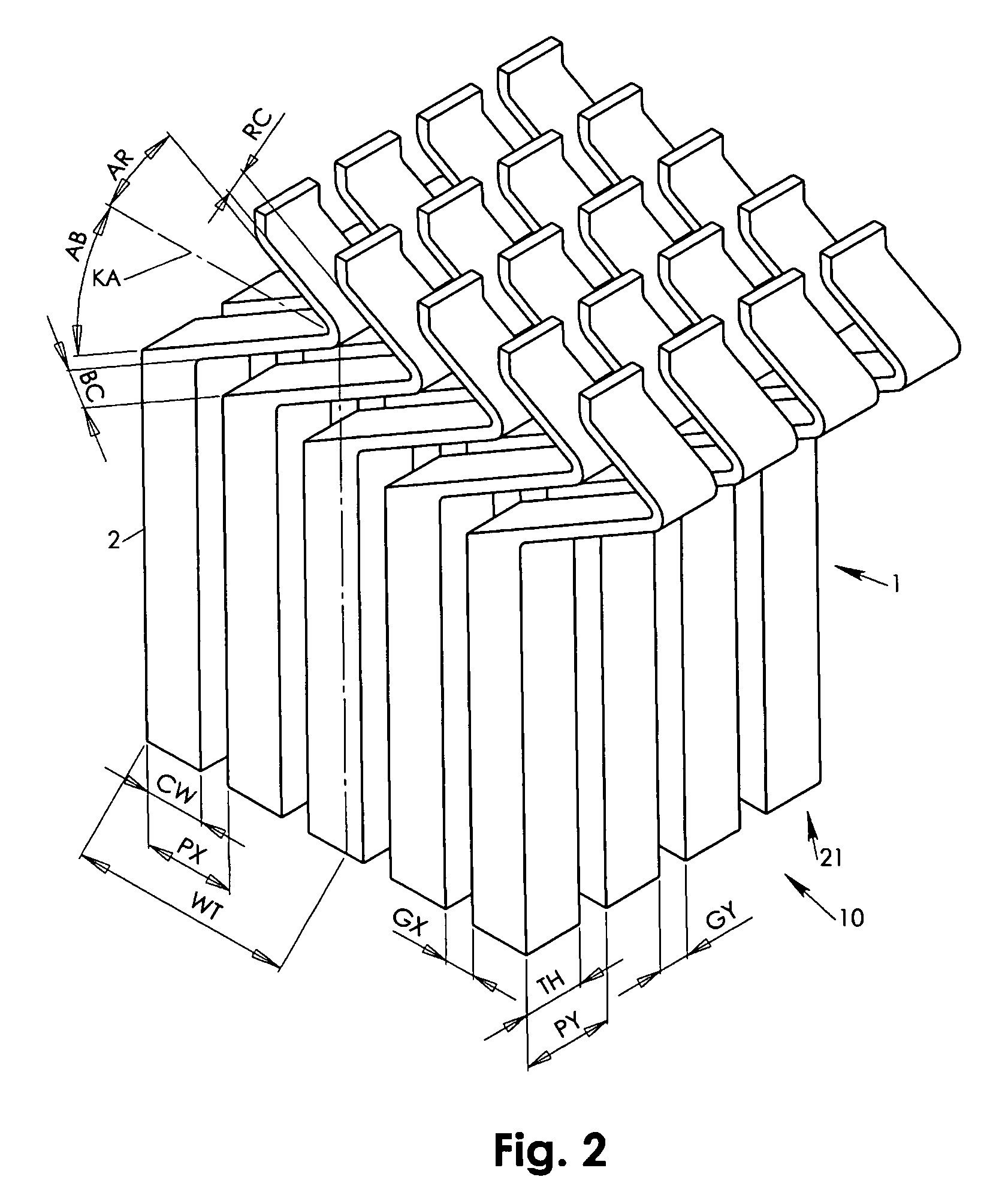
[0025] Referring to FIG. 1, a probe 1 in accordance with a preferred embodiment of the invention features a rigid columnar structure 2 having a peripheral end 21, a connect end 22, a knee opposing face 23, a connect face 24, a front face 25 and a back face 26. The columnar structure 2 is preferably symmetric with respect to a central column axis CA. At the connect end 22, a suspension knee 3 is laterally connecting via its base arm 32, which propagates away from the column axis CA substantially up to a lateral knee extension PK. A reverse arm 34 continues from the base arm 32. The reverse arm 34 propagates away from the lateral knee extension PK in direction towards the column axis CA with a reverse length RL. At the end of the reverse arm 34 is a contacting tip 35. The contacting tip 35 has a contacting face 36 with a tip axis TA central with respect to the contacting face 36. The tip axis TA is offset from the column axis CA in a tip offset TO. The tip offset TO is smaller than th...


PUM


Abstract

A rigid column and a suspension knee are combined in a probe held in assembly via its column. The suspension knee has a base arm laterally connecting at and propagating away from the column. The base arm extends up to a lateral knee extension where a reverse arm continues from the base arm back in direction towards a central axis of the column. The reverse arm terminates in a contact tip in a tip offset to the column axis that is smaller than the lateral knee extension. During application of a contacting force onto the contact tip, a first deflection of the base arm and a second deflection of the reverse arm counter act in conjunction with base and reverse arms' structural configurations. As a result, scrub motion may be well defined in direction and magnitude without need for additional guidance of the deflecting probe structure.

Description

FIELD OF INVENTION [0001] The present invention relates to probes for testing electronic circuitry. Particularly, the present invention relates to vertical probes having a rigid columnar structure and a suspension knee for controlled scrub motion. BACKGROUND OF INVENTION [0002] In the field of electronic circuitry testing, scrubbing and contact force is an important factor in establishing a low resistance electrical contact between a probe tip and the test contact. During scrubbing, an eventual insulating oxide layer is removed in the interface between the contact tip and the test contact. Scrubbing is a microscopic shear movement of the probe tip along the test contact surface while a certain pressure is exerted from the probe tip onto the test contact. As size and pitch of test contacts decrease, it becomes increasingly difficult to tune the scrub motion irrespective of friction influences in the tip / contact interface. Also, as the IC manufacturers incorporate designs with I.C. pa...

Claims


Application Information

Patent Timeline
IPC IPC(8): G01R1/067G01R1/073G01R31/02
CPCG01R1/07357G01R1/06733
Inventor KISTER, JANUARY
Owner MICRO PROBE
Why Eureka
Try Eureka