Nondestructive inspection method and apparatus

a non-destructive inspection and inspection method technology, applied in the direction of optically investigating flaws/contamination, instruments, computing, etc., can solve the problems of difficult differentiation between materials and flaws, inability to properly perform image pickup, etc., to facilitate the determination of true flaws

Inactive Publication Date: 2005-11-24
HITACHI-GE NUCLEAR ENERGY LTD
View PDF5 Cites 13 Cited by
  • Summary
  • Abstract
  • Description
  • Claims
  • Application Information

AI Technical Summary

Benefits of technology

[0010] An object of the present invention is to provide a flaw inspection method, a flaw inspection apparatus, and a flaw inspection assisting method that solve the above-described problems and facilitate determination of true flaws.
[0011] Another object of the present invention is to provide a flaw inspection method, a flaw inspection apparatus and a flaw inspection assisting method that readily discerns the location of a flaw, even in a large object under inspection.

Problems solved by technology

Note that if an unmodified color video camera is used in liquid penetrant inspection, image pickup cannot be properly performed because of reflected light from the illuminated object.
Further, in magnetic particle testing, all the foreign materials and the like on the object under inspection emit light due to illumination by ultraviolet light, making differentiation between these materials and the flaws difficult.

Method used


Image

  • Nondestructive inspection method and apparatus
  • Nondestructive inspection method and apparatus
  • Nondestructive inspection method and apparatus

Examples


Embodiment Construction

[0040] Hereinafter, an example of the present invention will be described with reference to the drawings.

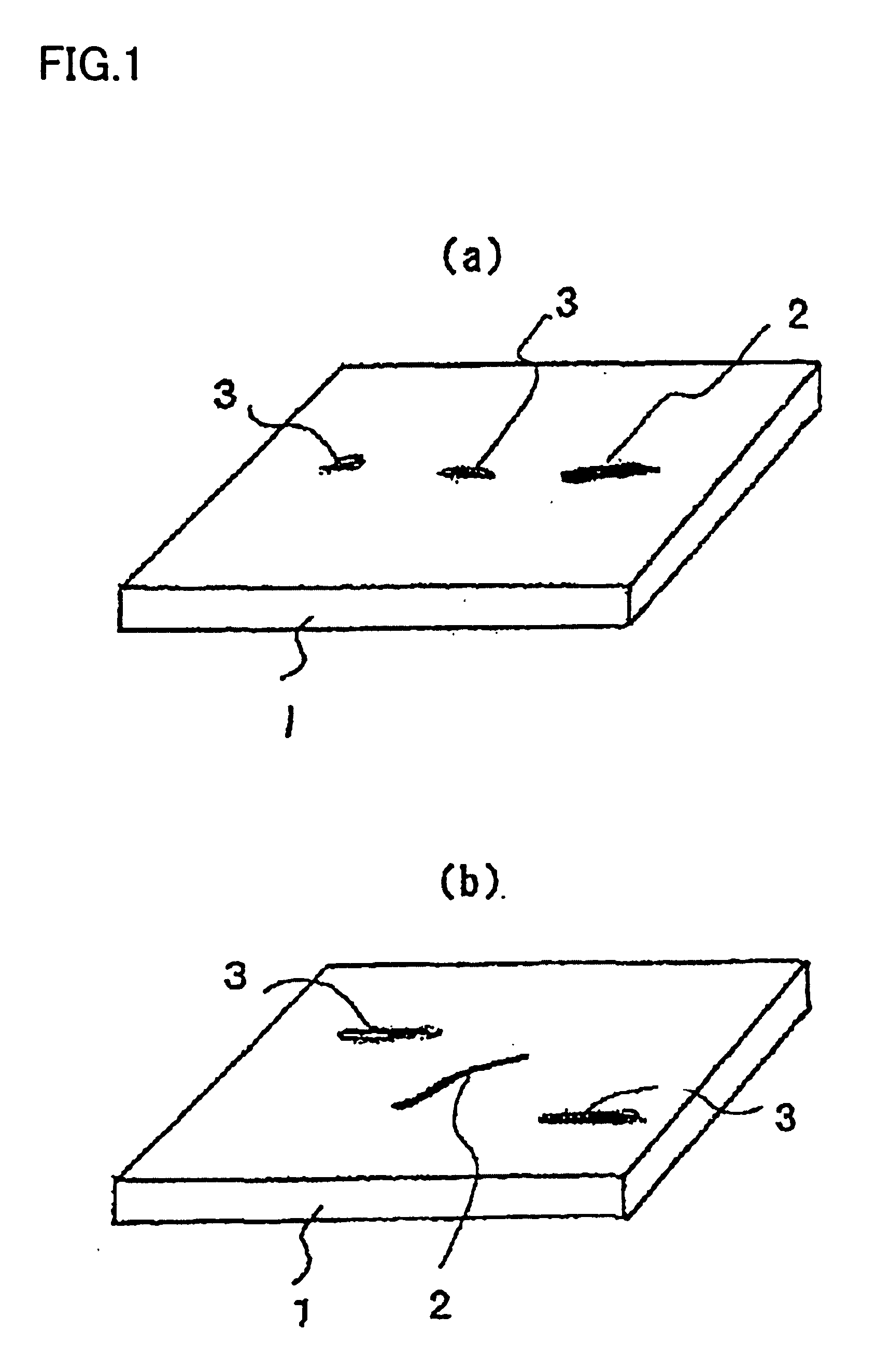
[0041] FIGS. 1(a) and (b) show an example of a flaw to be inspected in accordance with the present invention.

[0042]FIG. 1(a) shows an example of liquid penetrant inspection. An object under inspection 1 (hereinafter “object 1”) is coated with white development liquid, and a flaw 2 (contrast: high) and a pseudo flaw 3 (contrast: low) are observed. In the liquid penetrant inspection, flaw 2 is enhanced and displayed as a red indication mark. The pseudo flaw appears as a pale red indication mark, such as when the penetrant has remained in a surface grinding streak or the like and has not been completely polished out.

[0043]FIG. 1(b) shows an example of magnetic particle testing. Fluorescent magnetic powder has been applied to object 1 having flaw 2, and the object has been magnetized. When the object is illuminated with ultraviolet light, the fluorescent magnetic powder collected ...


PUM

PropertyMeasurementUnit
sizeaaaaaaaaaa
liquid penetrant testingaaaaaaaaaa
color cameraaaaaaaaaaa

Abstract

The present invention relates to a method for inspecting a crack in a metal surface or the like, and, particularly, to an inspection method and apparatus for nondestructive inspection such as liquid penetrant inspection and magnetic particle testing. The present invention provides a flaw inspection method that essentially comprises the steps of illuminating a surface of a sample to be inspected, obtaining an image of the surface, characterizing a potential flaw on the inspected surface by processing the obtained image, displaying an image of the potential flaw, verifying that the potential flaw is a true flaw, and storing an image of the verified flaw in memory.

Description

CROSS-REFERENCES TO RELATED APPLICATIONS [0001] The present application is a continuation application which claims priority to U.S. application Ser. No. 09 / 698,810, filed Oct. 26, 2000, and claims priority from Japanese Patent Application Reference No. 11-303480, filed Oct. 26, 1999.BACKGROUND OF THE INVENTION [0002] The present invention relates to a method for inspecting a crack in a metal surface or the like, and particularly, to an inspection method and apparatus for nondestructive inspection such as liquid penetrant inspection and magnetic particle testing. [0003] Liquid penetrant inspection and magnetic particle testing are nondestructive inspection methods for inspecting a flaw such as a fracture (crack) in a metal surface. In the liquid penetrant inspection, a red liquid (“penetrant”) is typically applied to an inspected surface. The penetrant is wiped off after a predetermined period, and a white powder (“developer”) is applied to the surface. If there is a flaw such as a c...

Claims


Application Information

Patent Timeline
Patent Type & Authority Applications(United States)
IPC IPC(8): G01N21/91G01N27/82G06V10/56
CPCG06K9/4652G01N21/91G06V10/56G01N27/82
Inventor NOMOTO, MINEOKATSUTA, DAISKEASANO, TOSHIOSAKAI, KAORUTAGUCHI, TETSUOTANAKA, ISAO
Owner HITACHI-GE NUCLEAR ENERGY LTD
Why Eureka
Try Eureka