Auxiliary instrument for fixing rod

a technology for fixing instruments and rods, applied in the field of auxiliary instruments for fixing rods, can solve the problems and achieve the effect of not being able to hurt an incision part of a patient and being able to screw the detent pin into the engaging groov

Inactive Publication Date: 2005-11-24
SHOWA IKA KOHGYO
View PDF14 Cites 111 Cited by
  • Summary
  • Abstract
  • Description
  • Claims
  • Application Information

AI Technical Summary

Benefits of technology

[0008] An object of the present invention is to provide an auxiliary instrument for fixing a rod capable of easily and stably screwing a detent pin into an engaging groove when the rod is fixed to an implant.
[0010] According to the present invention, the auxiliary instrument prevents the detent pin from wobbling because the inner cylinder accommodates the detent pin at a time of screwing the detent screw into an engaging groove formed on the head portion of the screw. It therefore becomes easier to screw the detent pin into the engaging groove. The auxiliary instrument further prevents the detent pin from falling from the engaging groove because the inner cylinder accommodates the detent pin at the time of screwing the detent pin into the engaging groove. It is therefore not possible to hurt an incision part of a patient.

Problems solved by technology

It is therefore not possible to hurt an incision part of a patient.

Method used


Image

  • Auxiliary instrument for fixing rod
  • Auxiliary instrument for fixing rod
  • Auxiliary instrument for fixing rod

Examples


first embodiment

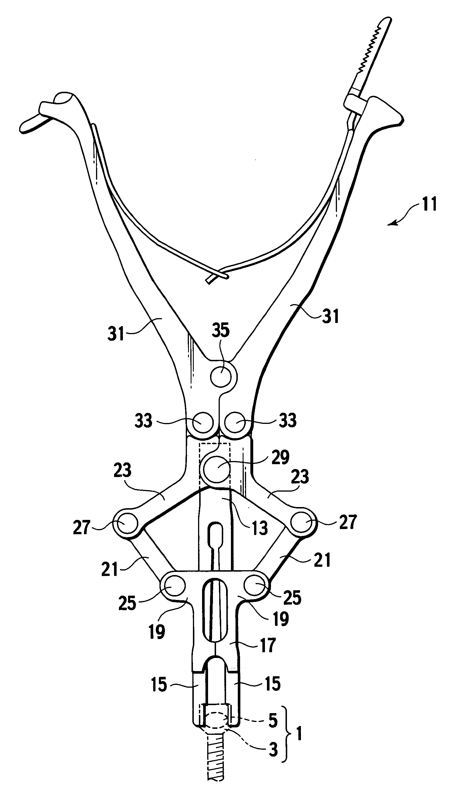
[0024] A bone connector 1 comprises implants (screws) 3, a rod 5 and a detent pin (not shown). An engaging groove (not shown) is formed on a square head portion of the screw 3. The rod 5 passes through a lower portion of the engaging groove.

[0025] As shown in FIGS. 3 and 4, an auxiliary instrument for fixing a rod 11 comprises an inner cylinder 13, claw portions 15, 15, 15, 15, an outer cylinder 17, brackets 19, 19, first links 21, 21, second links 23, 23, first hinge pins 25, 25, second hinge pins 27, 27, a first pivot 29, levers 31, 31, third hinge pins 33, 33 and a second pivot 35.

[0026] The inner cylinder 13 branches in four directions as gently inclining outward from the vicinity of a center portion thereof. The inner cylinder 13 further has the claw portions 15, 15, 15, 15 at distal ends of branch parts thereof (a lower end of the inner cylinder 13). The head portion of the screw 3 is sandwiched between the claw portions 15, 15, 15, 15. The outer cylinder 17 is arranged conc...

second embodiment

[0036] A bone connector 51 comprises implants (screws) 53, a rod 55 and a detent pin 57 (see FIG. 8A). The screw 53 is screwed into a vertebral body such as a thoracic vertebra and a lumbar vertebra. The rod 55 connects a plurality of screws 53 one another. The detent pin 57 fixes the rod 55 to each of the screws 53.

[0037] As shown in FIG. 5, the screw 53 has a thread portion 53A, a head portion 53B, an engaging groove 53C, a female thread portion 53D and engaging holes 53E, 53E. The thread portion 53A to be screwed into the vertebral body is formed at a lower part of the screw 53. The square head portion 53B is formed at an upper part of the screw 53. The engaging groove 53C is formed at a center part of the head portion 53B. The rod 55 passes through a lower portion of the engaging groove 53C. The female thread portion 53D is formed on an upper part of an inner surface of the engaging groove 53C. A male thread portion (not shown) formed on an outer surface of the detent pin 57 is...


PUM


Abstract

An auxiliary instrument for fixing a rod places a detent pin on a head portion of the screw. The auxiliary instrument comprises an inner cylinder, an outer cylinder, a first lever and a second lever. The inner cylinder has a plurality of claw portions and an opening employed to introduce the detent pin into an interior thereof. The outer cylinder is arranged to surround the inner cylinder and has a claw pressing portion. The first lever is rotatably connected to the inner cylinder and arranged in substantially perpendicular to an axial direction of the inner cylinder. The second lever is rotatably connected to the fist lever and the outer cylinder and arranged in substantially perpendicular to an axial direction of the outer cylinder. When the first and second levers are operated, the claw portions are pressed inward by the claw pressing portion to hold the head portion of the screw.

Description

CROSS REFERENCE TO RELATED APPLICATION [0001] This application claims benefit of priority under 35 U.S.C. § 119 to Japanese Patent Application No. 2004-66311, filed on Mar. 9, 2004, the entire contents of which are incorporated by reference herein. BACKGROUND OF THE INVENTION [0002] 1. Field of the Invention [0003] The present invention relates to an auxiliary instrument for fixing a rod, which connects bones such as thoracic vertebrae or lumbar vertebrae, in engaging grooves which each is formed on a head portion of an implant (a screw) screwed into the bone. [0004] 2. Description of the Related Art [0005] In a conventional bone connector, as shown in FIGS. 1 and 2, a vertebral body 101 is integrally connected to an adjacent vertebral body 101 by screwing implants (screws) 103 into the vertebral bodies 101 and then fixing a rod 105 to head portions of the screws 103. [0006] A work for fixing the rod 105 to each of the screws 103 will be described in detail below. Firstly, the rod 1...

Claims


Application Information

Patent Timeline
Patent Type & Authority Applications(United States)
IPC IPC(8): A61B17/58A61B17/88B25B23/10
CPCA61B17/7086A61B17/60A61B17/68
Inventor ORIBE, KAZUYATAKAMIDO, HIROSHI
Owner SHOWA IKA KOHGYO
Why Eureka
Try Eureka