
Artificial expansile total lumbar and thoracic discs for posterior placement without supplemental instrumentation and its adaptation for anterior placement of artificial cervical, thoracic and lumbar discs

a technology of total lumbar and thoracic discs and anterior placement of artificial discs, applied in the field of artificial discs, can solve the problems of limited placement, limited single-level replacement, and significant risk of retrograde ejaculation

Inactive Publication Date: 2005-11-24
MOSKOWITZ NATHAN C
View PDF20 Cites 245 Cited by
  • Summary
  • Abstract
  • Description
  • Claims
  • Application Information

AI Technical Summary

Benefits of technology

"The present invention relates to artificial discs for replacing damaged spinal discs. The technical effects of this patent include the development of total lumbar artificial discs that can be placed posteriorly without supplemental instrumentation, and anteriorly in the cervical spine without anterior screw fixation. The design of these discs allows for multi-level disc replacement and reduces the risk of complications such as retrograde ejaculations and vascular injury. Additionally, the invention provides a method for safely and successfully placing artificial lumbar discs throughout the entire lumbar spine."

Problems solved by technology

However based on the current anterior cervical prosthetic disc screw fixation methodology its implantation is periodically complicated by screw failures e.g. partial or complete screw pullouts or breaks, and in most designs it is limited to single level replacement.
Furthermore, for lumbar total artificial discs, placement is limited to only the L4 / 5 and L5 / S1 disc spaces, and not above, secondary to aortic and vena caval anatomical restraints.
Furthermore, despite the purported safety of placement of the current total lumbar artificial discs, there is a significant risk of retrograde ejaculations in males, and the risk of vascular injury, which although small, is potentially catastrophic if it occurs.
Their major limitation is the lack of elasticity and shock absorption capacity.
On the other hand, their long term durability beyond ten years is not currently known.
Furthermore by so doing, the probability of recurrent herniation plummets, and subsequently the need for posterior pedicle instrumentation plummets, thereby diminishing overall spinal morbidity, expenditure, and leading to the overall improvement in the quality of life.
Presumably up to now, technology is not focusing on posterior placement of total lumbar prosthetic discs because of inadequate access to the disc space posteriorly.
The approach of posteriorly placing artificial disc cores appears to be flawed in that: 1) there is a high extrusion rate, 2) it lacks good fixation as does total prosthetic devices that are placed anteriorly, 3) it is restricted only to early symptomatically disrupted discs which have only nucleus pulposus but not annulus or endplate pathology, and 4) are contraindicated in discs with an interspace height of less than 5 mm.

Method used


Image

  • Artificial expansile total lumbar and thoracic discs for posterior placement without supplemental instrumentation and its adaptation for anterior placement of artificial cervical, thoracic and lumbar discs
  • Artificial expansile total lumbar and thoracic discs for posterior placement without supplemental instrumentation and its adaptation for anterior placement of artificial cervical, thoracic and lumbar discs
  • Artificial expansile total lumbar and thoracic discs for posterior placement without supplemental instrumentation and its adaptation for anterior placement of artificial cervical, thoracic and lumbar discs

Examples


Embodiment Construction

[0024] The Medical Device

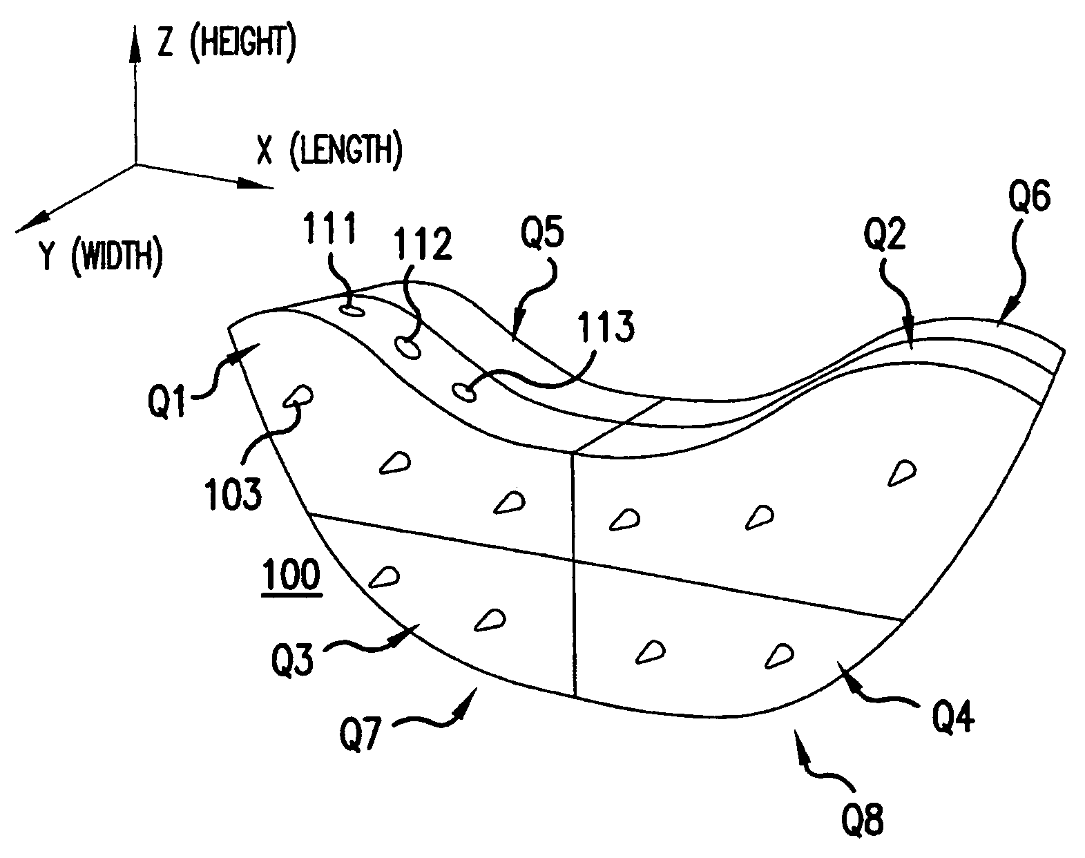
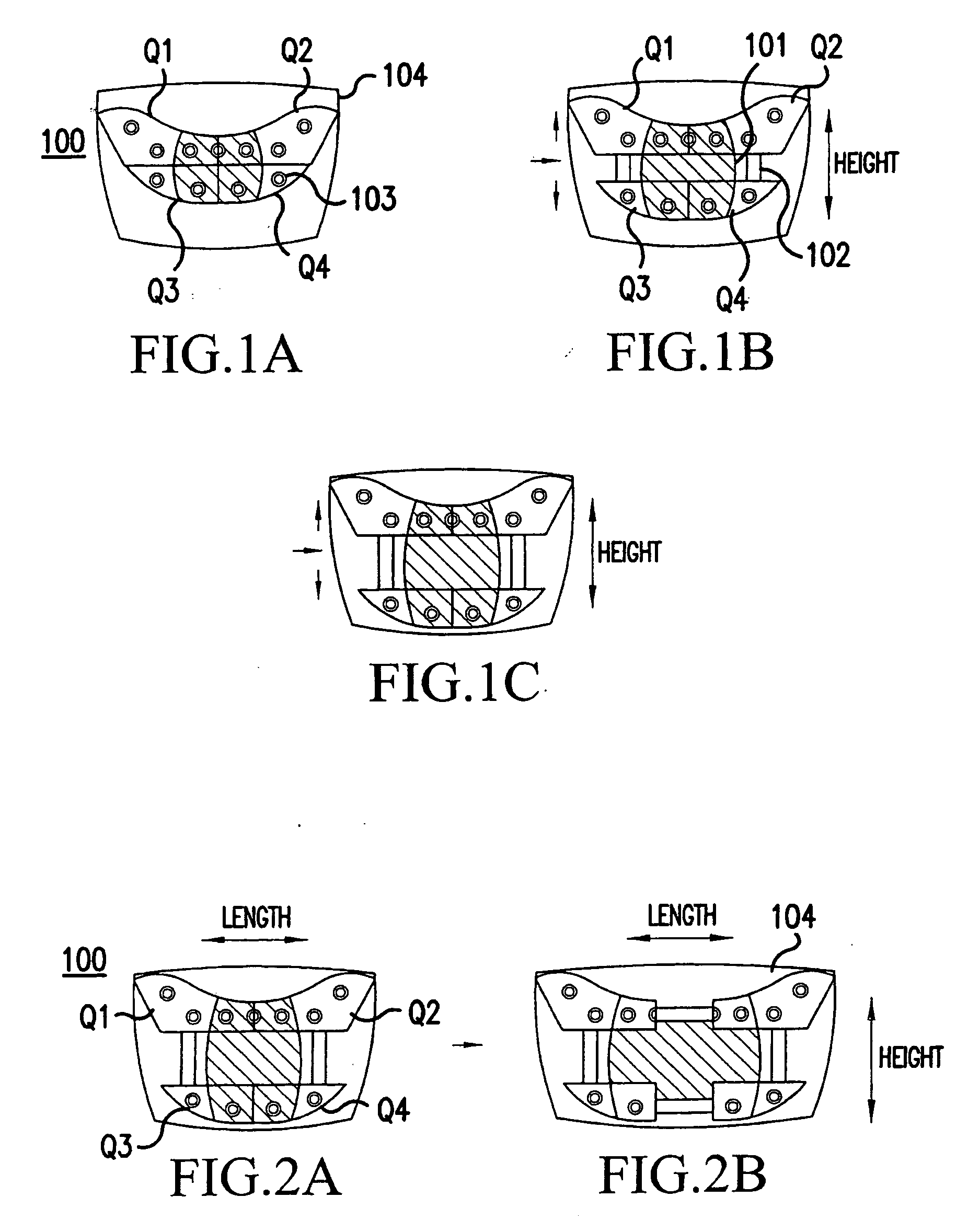
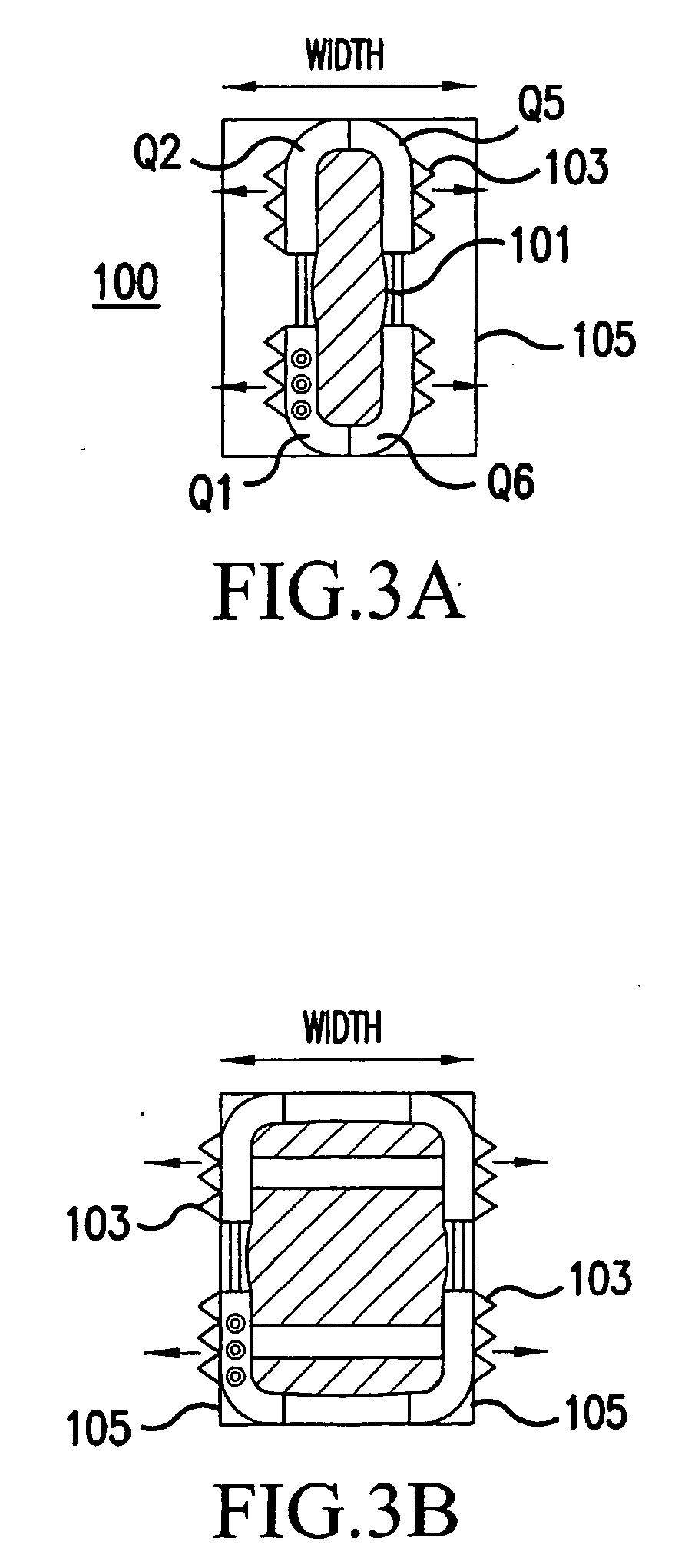
[0025] Referring now to FIGS. 1-4, the above described problem can be solved in the lumbar / thoracic spine by the insertion of a total boomerang (bean) shaped prosthetic disc 100 including an expansile disc core 101 surrounded by ratchetable titanium shells (containers) Q1-Q8 that can expand geometrically in all three x, y, and z planes, horizontally, vertically and width wise.

[0026] The outer titanium shells Q1-Q8 themselves when ratcheted width-wise have titanium spikes 103 inserting themselves into and purchasing the endplates, thus securing permanent integration into the vertebral endplates. The outer shell titanium surfaces can be treated with hydroxyappetite to facilitate bone incorporation. There is currently available a vertebral ratcheting corpectomy construct which can be ratcheted up vertically until it purchases the rostral and caudal endplates with spikes. There are currently transpedicular / posterior lumbar interbody fusion (T / PLIF) bean shaped...


PUM

PropertyMeasurementUnit
heightaaaaaaaaaa
elasticaaaaaaaaaa
convex shapeaaaaaaaaaa

Abstract

A total artificial expansible disc having at least two pairs of substantially parallel shells, which move in multiple directions defined by at least two axes, is disclosed. Several methods for implanting the total artificial expansile disc are also disclosed. The total artificial expansile disc occupies a space defined by a pair of vertebral endplates. An expansion device, which preferably includes a jackscrew mechanism, moves the pairs of shells in multiple directions. A core is disposed between the pairs of shells, and the core permits the vertebral endplates to move relative to one another.

Description

[0001] This application is continuation-In-Part of copending application Ser. No. 10 / 964,633, filed on Oct. 15, 2004, which claims the benefit under Title 35, U.S.C. §119 (e) of U.S. provisional application 60 / 578,319 filed on Jun. 10, 2004; 60 / 573,346 filed on May 24, 2004; 60 / 572,468 filed on May 20, 2004; 60 / 570,837 filed on May 14, 2004; and 60 / 570,098 filed on May 12, 2004, the entire contents of which are hereby incorporated by reference and for which priority is claimed under 35 U.S.C. § 120.BACKGROUND OF THE INVENTION [0002] 1. Field of the Invention [0003] The present invention relates to artificial discs, and more specifically relates to artificial expansile total lumbar and thoracic discs for posterior placement without supplemental instrumentation, and to anterior placement of artificial discs for the cervical, thoracic and lumbar spine. [0004] 2. Description of the Relevant Art [0005] Cervical and lumbar total artificial discs are entering the clinical neurosurgical and...

Claims


Application Information

Patent Timeline
Patent Type & Authority Applications(United States)
IPC IPC(8): A61B17/00A61B17/32A61B17/56A61B17/88A61F2/00A61F2/02A61F2/28A61F2/30A61F2/44
CPCA61B2017/00261Y10S606/91A61F2/442A61F2/4425A61F2/4465A61F2/447A61F2002/2817A61F2002/30062A61F2002/30133A61F2002/30507A61F2002/30518A61F2002/30522A61F2002/30523A61F2002/3055A61F2002/30556A61F2002/30563A61F2002/30579A61F2002/30583A61F2002/30601A61F2002/30604A61F2002/30616A61F2002/30649A61F2002/30841A61F2002/30919A61F2210/0004A61F2210/0085A61F2220/0025A61F2230/0015A61F2250/0007A61F2250/0009A61F2310/00017A61F2310/00023A61F2310/00029A61F2310/00796Y10S606/907A61F2/441
Inventor MOSKOWITZ, NATHAN C.MOSKOWITZ, MOSHEH
Owner MOSKOWITZ NATHAN C
Learn More