
Failure diagnosis method, failure diagnosis apparatus, conveyance device, image forming apparatus, program, and storage medium

a technology of failure diagnosis and failure, applied in the field of failure diagnosis method, failure diagnosis apparatus, conveyance device, image forming apparatus, program, etc., can solve the problems of large amount of labor required for solving, large variability of input information, and inability to accept failures

Active Publication Date: 2005-11-24
FUJIFILM BUSINESS INNOVATION CORP
View PDF38 Cites 105 Cited by
  • Summary
  • Abstract
  • Description
  • Claims
  • Application Information

AI Technical Summary

Benefits of technology

The invention is a failure diagnosis method and apparatus for diagnosing failures in a device with a drive mechanism. The method involves automatically collecting data on the device's operation and analyzing it based on a model of failure probability to identify potential issues with each component of the drive mechanism. The apparatus includes a failure diagnosis section that automates this process. The technical effect of this invention is to provide a reliable and efficient way to diagnose failures in devices with drive mechanisms, which can help to prevent damage and improve overall performance.

Problems solved by technology

Recently, in office equipment such as, for example, a copying machine or a printer, high productivity is demanded, so that delays due to failures are not acceptable and it has been demanded that a failure is quickly detected and solved.
Particularly, when the use environment is poor, even in a normal method of use, various abnormalities and failures that are hardly detected occur, and a large amount of labor is necessary for solving them.
Therefore, in this method, if a customer who makes an examination does not get used to this method, there is fear that input information greatly varies, that an accurate diagnosis cannot be executed, and that serious false diagnosis may be caused.
Furthermore, since many actions are assigned to a user, the user may feel a great deal of stress.

Method used


Image

  • Failure diagnosis method, failure diagnosis apparatus, conveyance device, image forming apparatus, program, and storage medium
  • Failure diagnosis method, failure diagnosis apparatus, conveyance device, image forming apparatus, program, and storage medium
  • Failure diagnosis method, failure diagnosis apparatus, conveyance device, image forming apparatus, program, and storage medium

Examples


Embodiment Construction

[0041] Hereinafter, embodiments of the invention will be described in detail with reference to the drawings.

[0042]>

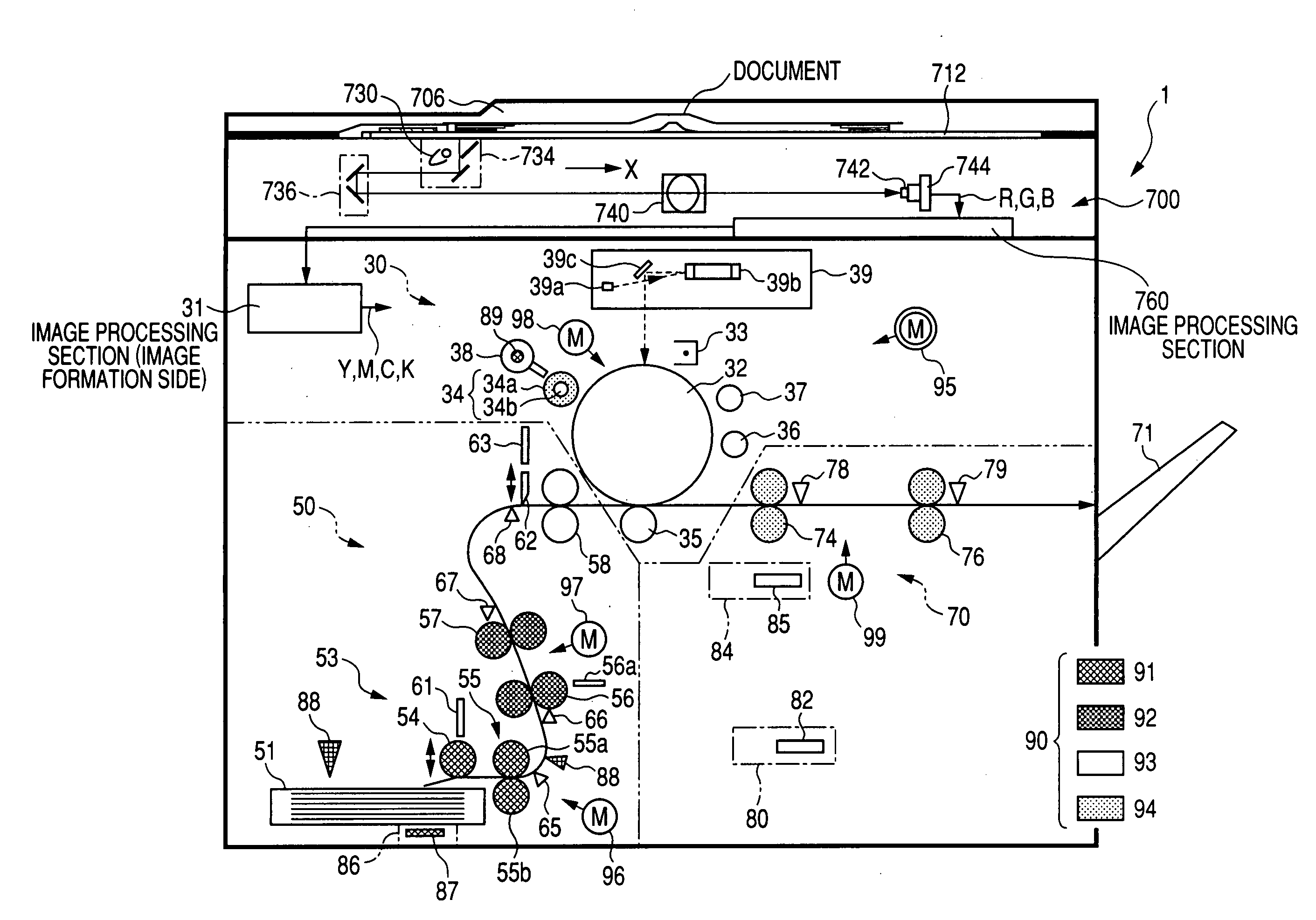
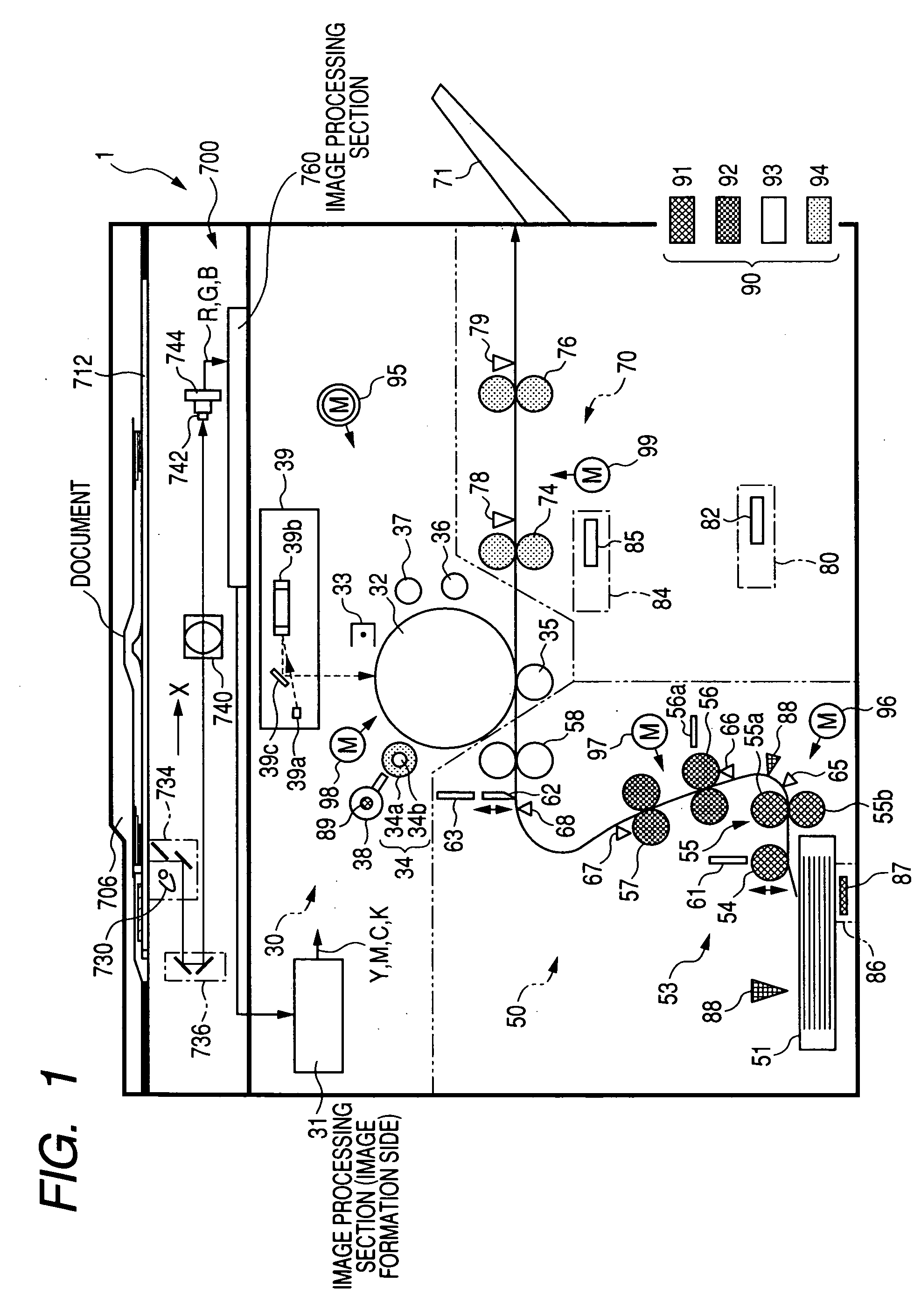
[0043]FIG. 1 shows a configuration example of an image forming apparatus equipped with a failure diagnosis apparatus according to an embodiment of the invention. This image forming apparatus 1 has an image reading section (scanner section) for reading an image on, for example, a document. The image forming apparatus 1 is a complex machine having a copying machine function for printing an image corresponding to a document image on the basis of image data read by the image reading section, a printer function for printing-out on the basis of printing data (data representing an image) input from a personal computer, and a facsimile transmission and reception function which can print out a facsimile image. The image forming apparatus 1 is configured as a digital printing unit.

[0044]FIG. 1 shows a sectional view of a mechanical part (hardware configuration), focusing on a f...


PUM


Abstract

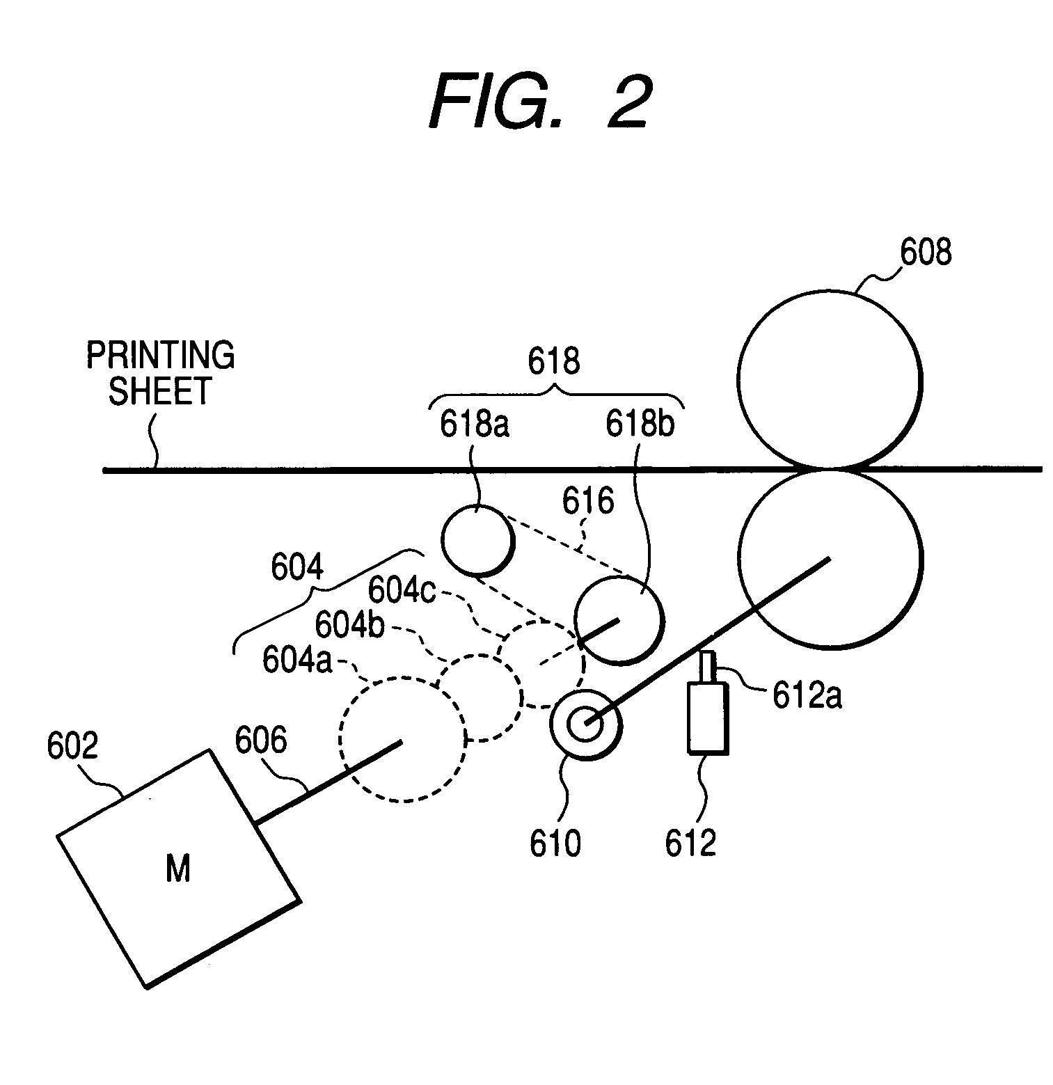
A failure diagnosis method diagnoses a failure occurring in a diagnosis target apparatus including a drive mechanism having a drive member that receives power supply to operate and a power transmission member that transmits drive force of the drive member to another member. The method includes automatically acquiring by a sensor an operation state signal indicating an operation state during the drive mechanism operating for a predetermined period; and analyzing the automatically acquired operation state signal based on a failure probability model, which is obtained by modeling a cause of failure occurring in the diagnosis target apparatus with using probabilities, to execute failure diagnosis with respect to each of constituent members of the drive mechanism.

Description

BACKGROUND OF THE INVENTION [0001] 1. Field of the Invention [0002] The present invention relates to a failure diagnosis method and a failure diagnosis apparatus for diagnosing a failure and malfunction of drive mechanism section used in an image forming apparatus having a conveyance device, such as a copying machine, a printer, a facsimile, or a complex machine having functions of these and other equipment (for example, electric appliances and automobiles); a conveyance device and an image forming apparatus to which the failure diagnosis method and the failure diagnosis apparatus are applied; and a program for realizing the failure diagnosis method and the failure diagnosis apparatus by using an electrical computer; and a storage (recording) medium storing the program. [0003] More specifically, the invention relates to a technique for automatically diagnosing a conveyance device and an image forming apparatus by modeling factors that cause devices / apparatuses to fail into an inform...

Claims


Application Information

Patent Timeline
Patent Type & Authority Applications(United States)
IPC IPC(8): G03G21/00B41J29/46G06F11/00
CPCG03G15/553G06F11/0733G03G15/5079G06F11/079G03G15/55G06F11/0748
Inventor YASUKAWA, KAORUADACHI, KOUJIUWATOKO, KOUKIYAMADA, NORIKAZUNAKAGAWA, EIGOSATONAGA, TETSUICHI
Owner FUJIFILM BUSINESS INNOVATION CORP
Learn More